All Categories

FPV Electronics > VTX & Receiver
FPV Electronics > VTX & Receiver
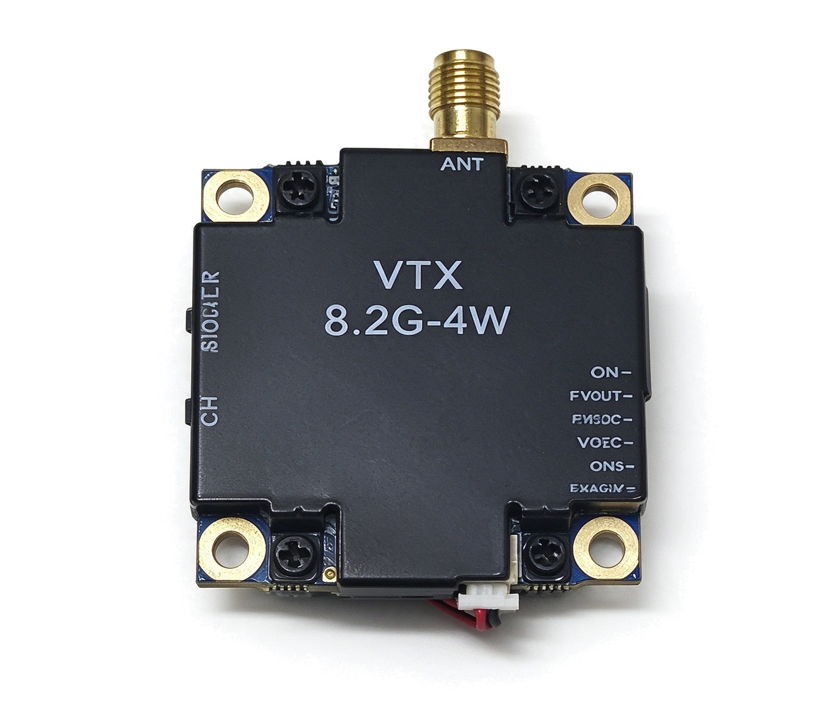
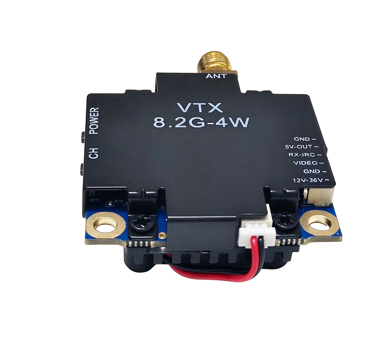
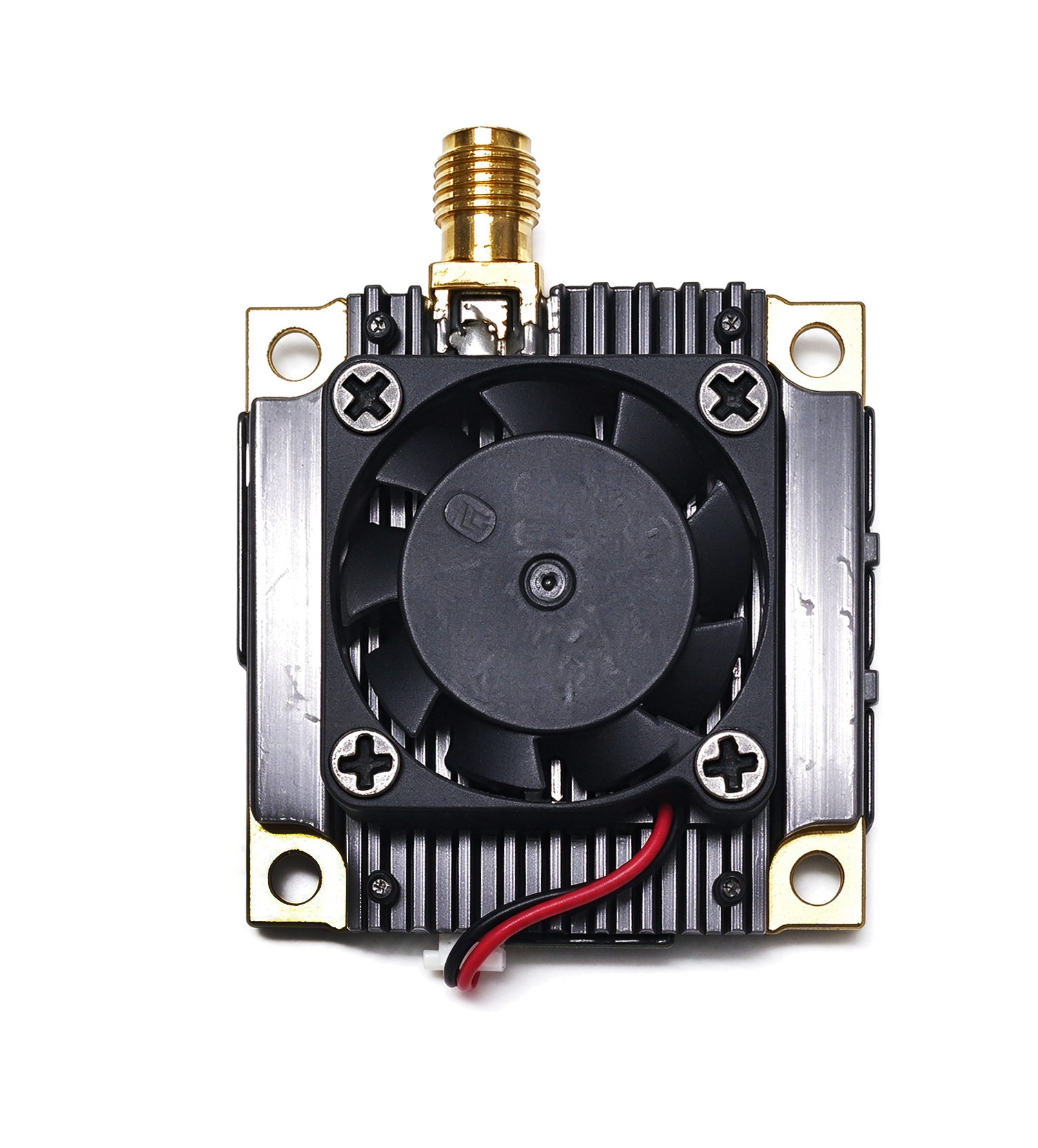
The VTX 8.2G-4W is a 4W analog audio and video transmitter operating in the 7.0 to 8.2 GHz band. It provides 56 channels across 7 frequency bands, three selectable output power levels of 200mW, 2W and 4W, and wideband FM modulation with NTSC and PAL video support. The module is built on a compact 36 x 48 x 15 mm PCB with a rear cooling fan, four corner mounting holes and an RP-SMA antenna connector, which makes it suitable for long range FPV, RC and industrial video links.
| Parameter | Specification |
|---|---|
| Model No. | VTX_8.2G-4W |
| Product Type | Analog audio and video transmitter (VTX) |
| Operating Frequency Band | 7.0 to 8.2 GHz |
| Output Power | 4W maximum (36 dBm) |
| Selectable Power Levels | 200mW / 2W / 4W (Level 1 / 2 / 3) |
| Total Channels | 56 CH (7 bands x 8 channels) |
| Frequency Bands | A, B, E, F, R, U, O |
| Modulation | Wideband FM |
| Video Format | NTSC / PAL |
| Video Bandwidth | 0 to 8.0 MHz |
| Video Input Level | 0.8 to 1.2 Vp-p (1.0 Vp-p typical) |
| Video Input Impedance | 75 Ω |
| Output Impedance | 50 Ω |
| Antenna Connector | RP-SMA |
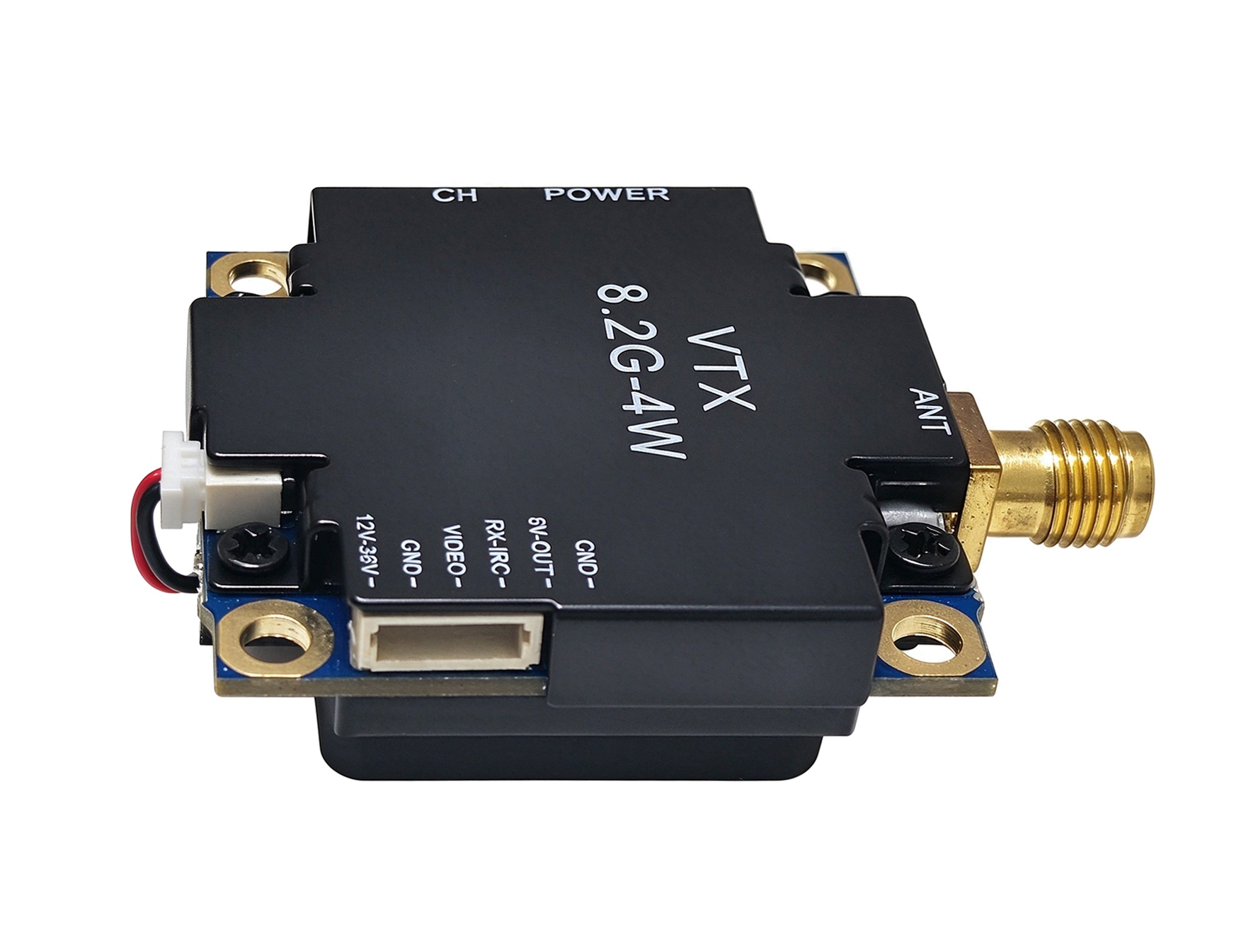
| Power and Video Connector | 5 pin harness: GND, 5V OUT, R-OUT, VIDEO, DC IN |
| Operating Voltage | 16 to 30V DC (24V typical) |
| Supply Current | 1.2A typical |
| Operating Temperature | -10 to +100°C |
| Dimensions | 36 x 48 x 15 mm (overall, including antenna connector) |
| Net Weight | 29g (excluding antenna) |
• 7.0 to 8.2 GHz operation: Seven overlapping bands cover 7000 MHz to 8210 MHz, giving a total of 56 switchable channels for interference avoidance.
• 4W RF output: Three selectable power levels of 200mW, 2W and 4W, with the module starting at the lowest level after power up.
• Wideband FM audio and video: NTSC and PAL support, 75 Ω video input impedance and 0 to 8.0 MHz video bandwidth.
• Camera power output: A 5V OUT pin on the harness can supply power to the camera.
• Wide DC input: 16 to 30V DC operating range at 1.2A typical supply current.
• Compact and light: 36 x 48 x 15 mm overall and 29g excluding the antenna.
• Mechanical design: Rear cooling fan, four corner mounting holes with gold plated inserts, and a top mounted RP-SMA connector.
• Thermal protection: Built in PTC temperature sensor with automatic power reduction and automatic recovery.
• Button and LED control: Channel, band and power are set from two buttons, with red, blue and green LED feedback.
| No. | Parameter | Min. | Typ. | Max. | Unit |
|---|---|---|---|---|---|
| 1 | Output Impedance | - | 50 | - | Ω |
| 2 | Output Power | 23.5 | 31.5 | 36 | dBm |
| 3 | Operating Voltage | 16 | 24 | 30 | V |
| 4 | Supply Current | - | 1.2 | - | A |
| 5 | Operating Temperature | -10 | - | 100 | °C |
| 6 | Video Bandwidth | 0 | - | 8.0 | MHz |
| 7 | Video Input Level | 0.8 | 1.0 | 1.2 | Vp-p |
| 8 | Video Input Impedance | - | 75 | - | Ω |
| Band | CH1 | CH2 | CH3 | CH4 | CH5 | CH6 | CH7 | CH8 |
|---|---|---|---|---|---|---|---|---|
| A (FR1) | 7000 | 7025 | 7050 | 7075 | 7100 | 7125 | 7150 | 7175 |
| B (FR2) | 7200 | 7225 | 7250 | 7275 | 7300 | 7325 | 7350 | 7375 |
| E (FR3) | 7400 | 7425 | 7450 | 7475 | 7500 | 7525 | 7550 | 7575 |
| F (FR4) | 7600 | 7625 | 7650 | 7675 | 7700 | 7725 | 7750 | 7775 |
| R (FR5) | 7800 | 7825 | 7850 | 7875 | 7900 | 7925 | 7950 | 7975 |
| U (FR6) | 8000 | 8025 | 8050 | 8075 | 8100 | 8125 | 8150 | 8175 |
| O (FR7) | 8210 | 8110 | 7910 | 7810 | 7610 | 7410 | 7210 | 7010 |
POWER button
• Short press: cycles power levels 1 / 2 / 3 (200mW / 2W / 4W). The module defaults to the lowest power level after power up.
• The red LED flashes slowly, and the number of flashes matches the current power level.
• Press and hold for 2 seconds: enters PPT mode. Press and hold again for 2 seconds to exit.
CH button
• Short press: cycles channels 1 to 8. The green LED flashes a number of times matching the current channel, with pauses between flash sequences.
• Press and hold for 2 seconds: enters band adjustment mode. Short press then switches between bands A / B / E / F / R / U / O. The blue LED flashes the current band, while the green LED flashes rapidly as a prompt.
• The module exits band adjustment mode and returns to the normal channel adjustment interface automatically if no button operation is performed within 30 seconds.
LED indicators
• R-LED (red): Power level
• B-LED (blue): Frequency band
• G-LED (green): Channel number
Overheating automatic protection
• A built in PTC temperature sensing resistor monitors the PCB main board.
• When the board temperature exceeds 120°C, the output power automatically drops to Level 1 (200mW) and the RGB tri-color indicator flashes rapidly as an alarm.
• When the temperature falls back to 100°C, the module automatically restores the power level set before.
Safety warning
• Do not power on the module without a frequency matched antenna installed, otherwise the RF module will be burned out immediately.