
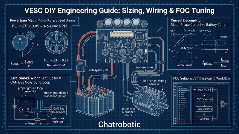
Quick Takeaway (TL;DR): Executing a reliable VESC DIY build requires matching battery nominal voltage and motor KV to the controller's breakdown ceiling, decoupling motor phase current from battery continuous current, and eliminating CAN bus ground loops in multi-motor setups. By transitioning from fragile legacy clones to modern production hardware starting at $59 (single-drive) and $99 (dual-drive), DIY builders can eliminate gate driver failures and achieve stable Field-Oriented Control (FOC) across electric skateboards, e-bikes, and mobile robotics.
1. The VESC DIY Landscape: Core Engineering Realities
Building a custom electric powertrain around the open-source VESC architecture gives makers, robotics engineers, and vehicle builders register-level control over torque, speed, and regenerative braking. Unlike locked commercial speed controllers with canned throttle curves, a VESC DIY build enables bidirectional current mapping, field weakening, custom sensor fusion, and real-time telemetry streaming over CAN bus or UART.
However, moving from off-the-shelf kits to an open hardware build introduces distinct power electronics constraints that commonly catch DIY builders off guard:
•Parasitic Inductance & Switching Transients: High-power DIY layouts often feature long battery wire runs between the energy storage pack and the inverter. Rapid PWM switching of phase currents creates severe inductive voltage spikes: V_spike = V_battery + [L_lead × (di/dt)] If these transients exceed the MOSFET drain-to-source breakdown rating (V_ds), the power stage suffers catastrophic punch-through.
•The CAN Ground-Loop Trap: When wiring dual controllers over CAN bus, connecting a redundant signal ground wire between two units that already share a common high-current battery ground creates a ground loop. During hard acceleration, return currents travel across the thin logic ground plane, instantly destroying CAN transceivers.
•The Low-Speed Torque vs. Battery Current Paradox: Novice builders frequently limit their motor current to match their battery pack's continuous discharge rating, resulting in sluggish launches and poor hill-climbing authority. In an FOC inverter, phase current and battery current are decoupled; understanding this relationship is vital to unlocking mechanical torque.
2. Powertrain Mathematics: Sizing Battery, Motor KV & Phase Current
Before mounting hardware, calculate mechanical and electrical limits to ensure the powertrain achieves desired operational speeds without exceeding component thermal boundaries.
Motor KV and Theoretical Wheel Speed
The relationship between battery voltage, motor velocity constant (KV), mechanical reduction, and linear vehicle speed is expressed by: Wheel Speed (km/h) = [Nominal Voltage (V) × Motor KV × (Driven Pulley Teeth ÷ Driving Pulley Teeth) × Wheel Circumference (m) × 60] ÷ 1000
•Street Electric Skateboards (12S–14S / 90mm wheels): Target 170KV–190KV motors paired with 15T:36T gearing to achieve a 45–52 km/h top-speed ceiling without excessive resistive copper losses.
•High-Torque Mountainboards & Pneumatic LEVs (12S–18S / 8-inch tires): Target 130KV–150KV motors paired with 4:1 or 5:1 gear reductions to prevent low-speed phase current saturation.
•72V High-Speed E-Bikes & Mopeds (20S–24S): Target 10KV–18KV per volt on direct-drive hub motors, or high-speed geared mid-drives running up to 5,000 RPM into primary reduction stages.
Decoupling Phase Current from Battery Current
In VESC Tool, Motor Current Max dictates electromagnetic torque, while Battery Current Max protects the chemical cells from over-discharge:
•Electromagnetic Torque: Torque (Nm) = 1.5 × Pole_Pairs × Magnetic_Flux_Linkage × I_phase
•Electrical Power: Power (W) = V_battery × I_battery
At zero or low speeds, the inverter functions as a step-down buck converter. Operating at a 20% duty cycle, a controller can safely deliver 100A Phase Current to provide maximum hill-climbing thrust while drawing only 20A from the battery pack. Builders can configure high starting torque without exceeding the continuous discharge limits of budget battery packs.
3. VESC DIY Hardware Selection Matrix
Selecting the right controller depends on operating voltage, motor count, and environmental exposure. The ChatRobotic VESC (100A~3000A) catalog provides production-grade options tailored to specific DIY application categories:
| DIY Build Category | Recommended Controller Model | Voltage Ceiling | Peak Phase Current | Continuous Current | Direct Price | Key Architectural Advantage for DIY |
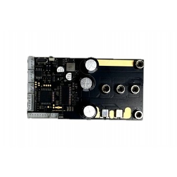
| Dual E-Skates & Differential AMRs | Dual VESC-LS 57V (14S) 300A | 57.0V–58.8V (14S) | 300A Total (150A/ch) | 120A/ch (240A total) | $99.00 ($49.50/axis) | Dual-MCU on one PCB; eliminates CAN ground loops & harness clutter. |
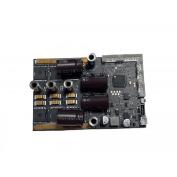
| Budget Single Commuters & 48V E-Bikes | VESC-LS 57V (14S) 300A V4 | 57.0V–58.8V (14S) | 300A Peak | 100A–120A cont | $59.00 | True 14S support; sub-$60 entry price beats generic 12S clones. |
| 72V E-Bikes & Compact LEVs | VESC-S 90V (21S) 300A V2 | 90.0V (21S) | 300A Peak | 120A cont | $129.00 | Ultra-compact 21S power stage fits narrow frame triangles. |
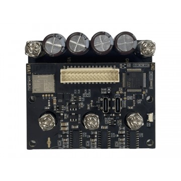
| Onewheel & Balance Conversions | X6 100V (22S) 315A VESC | 100.0V (22S) | 315A Peak | 120A cont | $179.00 | Built-in 6-axis IMU + Bluetooth; DRV-less EV discrete gate drive. |
| Extreme Voltage Balance Builds | X6 150V (32S) 171A VESC | 150.0V (32S) | 171A Peak (10s) | 120A cont | $199.00 | 150V breakdown protection against high-speed regenerative spikes. |
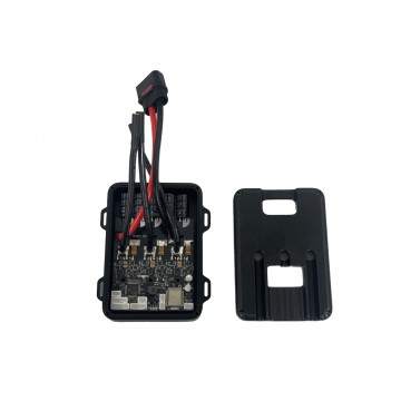
| All-Weather 72V–96V E-Bikes | TRONIC 250R 125V 300A (With Case) | 125.0V (27S) | 300A Peak | 150A cont | $230.00 | Hybrid CNC aluminum base + nylon top; direct chassis mounting. |
| High-Power E-Motos (Sur-Ron Class) | X6 120V (26S) 662A VESC | 120.0V (26S) | 662A Peak | 250A cont | $299.00 | 660A+ burst punch; replaces restrictive stock controllers. |
Pairing these controllers with ChatRobotic LandDrive Series Motors ensures factory-balanced stators and matched low-inductance phase windings, preventing FOC flux-observer drift during aggressive acceleration.
4. Five Core VESC DIY Application Blueprints
Deploying a successful build requires tailoring electrical topologies to physical use cases:
Blueprint 1: The $99 Dual-Motor Street Skateboard & Differential AMR
•Controller: Dual VESC-LS 57V (14S) 300A ($99.00).
•Powertrain Target: 12S Li-ion (50.4V peak) or 14S Li-ion (58.8V peak) driving dual 6355 or 6374 outrunner motors.
•Engineering Advantage: Sourcing two separate budget controllers typically costs over $140 and introduces external CAN wiring risks. The Dual VESC-LS integrates dual MCUs onto a single circuit board, driving two motors independently for an effective cost of $49.50 per motor axis. It eliminates external CAN interconnects, dual power harnesses, and ground-loop transceiver damage.
Blueprint 2: The Under-$60 Lightweight 14S Commuter & Small Rover
•Controller: VESC-LS 57V (14S) 300A V4 ($59.00).
•Powertrain Target: 36V, 48V, or 52V battery packs driving single hub motors or mid-drives up to 2.5 kW.
•Engineering Advantage: While generic 12S clones on marketplace storefronts sell for $65–$80 and easily fail near 50V, the VESC-LS V4 natively supports up to 14S (58.8V peak) with 300A burst capability at just $59.00. It is the benchmark entry-level single-axis inverter for budget e-bikes, delivery rovers, and single-drive e-skates.
Blueprint 3: The 72V High-Velocity Stealth E-Bike & Hardtail
•Controller: VESC-S 90V (21S) 300A V2 ($129.00) or TRONIC 250R 125V 300A With Case ($230.00).
•Powertrain Target: 72V (20S Li-ion / 84.0V peak) direct-drive hubs or geared mid-drives (e.g., CYC X1 Pro, Bafang Ultra M620).
•Engineering Advantage: A 72V pack easily spikes past 88V during high-speed regenerative braking. The VESC-S provides 90V headroom in an ultra-compact footprint that fits narrow frame triangles, while the TRONIC 250R provides 125V headroom and an aluminum/nylon case for direct frame mounting.
Blueprint 4: The Vibration-Proof Onewheel & Self-Balancing DIY Conversion
•Controller: X6 100V (22S) 315A VESC ($179.00) or X6 150V (32S) 171A VESC ($199.00).
•Powertrain Target: 18S to 20S (75.6V–84.0V) custom balance batteries driving high-pole hub motors (e.g., CannonCore, HyperCore).
•Engineering Advantage: Single-wheel balance boards experience violent curb strikes and footpad chatter. Sourcing external IMU breakout boards creates flying-lead failure points. The X6 series integrates a built-in 6-axis IMU, onboard Bluetooth, a DRV-less EV-grade discrete gate driver, and M5 screw terminals, delivering an all-in-one balance package that eliminates external breakout wiring.
Blueprint 5: The High-Torque E-Moto (Sur-Ron / Talaria Monster Build)
•Controller: X6 120V (26S) 662A VESC ($299.00).
•Powertrain Target: 72V–96V high-discharge battery packs powering IPM or PMSM mid-drive motors up to 20 kW.
•Engineering Advantage: Unlocking full motor performance requires continuous currents exceeding 250A and burst phase currents exceeding 600A. The X6 120V 662A delivers massive current margins on heavy-copper busbars, preventing thermal derating during sustained hill climbs.
5. Bench Wiring & Hardware Setup: Zero-Smoke Architecture
Follow a methodical physical wiring sequence to prevent transient shorts, ground loops, and signal corruption.
1. The DC Power Stage & Anti-Spark Protection
•Always integrate an anti-spark connector (such as XT90-S or QS8-S) or an active pre-charge solid-state switch between the battery pack and inverter. Hot-plugging a 12S–20S pack without inrush limiting causes instant contact pitting and induces voltage transients that threaten gate driver bootstrap circuits: I_inrush = (V_battery - V_capacitor) ÷ R_loop
•Keep DC battery leads as short as possible (under 15 cm). If battery placement forces longer runs, install a low-ESR electrolytic capacitor bank directly across the controller's DC input terminals to absorb switching ripple.
2. Multi-Motor CAN Bus Interfacing (The Golden Rule)
When synchronizing two or more independent VESC controllers (such as two single units) over CAN bus:
•Connect Only CAN_H and CAN_L: Never run a ground wire through the CAN cable if both controllers already share a common battery negative lead. Redundant ground paths establish a high-current loop during phase switching that will burn out the CAN transceiver chips.
•Dual-Drive Alternative: Deploying an integrated dual-inverter such as the Dual VESC-LS 57V (14S) 300A ($99.00) eliminates external CAN wiring entirely, handling inter-MCU communication across an internal, shielded copper trace.
3. Logic & Sensor Harness Routing
•Phase Wire Isolation: Route the high-current phase lines (U, V, W) away from low-voltage logic lines (Hall sensor, ADC throttle, UART/PPM receiver). If lines must intersect, cross them at 90-degree angles to minimize electromagnetic interference (EMI).
•Twisted Signal Pairs: Twist signal leads with their respective ground returns (e.g., ADC signal twisted with logic ground) to improve common-mode noise rejection.
6. Step-by-Step VESC Tool Commissioning Guide
Follow this standardized setup workflow to configure Field-Oriented Control without risking overcurrent trips.
Step 1: Initial Power-Up on Current-Limited Bench Supply
1. Never perform initial motor detection on a high-capacity, unprotected lithium pack.
2. Connect the controller to a benchtop DC power supply set to 24V–36V with current limiting clamped to 1.5A–2.0A.
3. Plug in a shielded USB-C data cable (or connect via the X6 Controller's onboard Bluetooth) and open the official VESC Tool.
Step 2: FOC Motor Detection Wizard
1. Elevate the driven wheel or disengage the drive belt/chain to ensure zero mechanical load.
2. Navigate to
Motor Settings -> FOC -> Generaland run the Setup Motors FOC wizard.3. Select the appropriate motor architecture (e.g.,
Large Outrunnerfor 63xx outrunners orDirect Drive / Hub Motorfor wheel hubs).4. Enter accurate physical motor parameters (stator weight in kg and pole pairs, typically 7 pairs for 14-pole outrunners; 15 to 23 pairs for hub motors).
5. Execute detection to measure:
•Phase Resistance (R): Measures winding resistance.
•Phase Inductance (L): Measures winding inductance.
•Flux Linkage (lambda): Measures the magnetic coupling between rotor and stator.
6. Apply and write the detected values to the controller.
Step 3: Sensor Detection & Commutation Mode
•Hall Sensors: Run the hall sensor detection routine. If detection fails, verify 5V logic supply continuity and check 10k-ohm pull-up resistors on sensor lines.
•Sensorless HFI (High-Frequency Injection): For sensorless builds requiring full standstill launch torque, configure Sensorless HFI mode. Inject a high-frequency tracking voltage (15V–25V at 25 kHz) to track rotor saliency without physical Hall sensors.
•Absolute Encoders (AS5047P / ABI): Ideal for robotics joints and precision actuators; calibrate index offsets to establish absolute zero on boot.
Step 4: Configuring Current Limits & Voltage Safeguards
In Motor Settings -> General -> Current:
•
Motor Current Max: Set based on motor thermal mass (e.g., 65A–80A for 6355 motors; 90A–120A for 6374/6384 motors; 150A+ for large hubs).•
Motor Current Max Brake: Set negative value (e.g., -60A to -80A) to establish maximum regenerative braking authority.•
Battery Current Max: Divide your pack's continuous safe discharge rating by the number of driven controllers (e.g., for a 100A pack driving a dual build, set 50A per side).•
Battery Current Max Regen: Set to safe pulse-charging rates (typically -15A to -25A per controller) to avoid cell plating.
In Motor Settings -> General -> Voltage:
•
Battery Voltage Cutoff Start: Set to 3.4V per cell (e.g., 40.8V for 12S, 68.0V for 20S) to initiate soft power reduction.•
Battery Voltage Cutoff End: Set to 3.1V per cell (e.g., 37.2V for 12S, 62.0V for 20S) to prevent deep-discharge cell damage.
Step 5: Input Mapping (Remote, Throttle & Multi-ESC Sync)
•PPM / UART Remotes: Set input mode to
Current No Reverse with Brakefor e-skate setups, orCurrent Reverse Centerfor bidirectional mobile robots.•Dual ESC CAN Synchronization:
•Designate the primary unit connected to the receiver as
CAN ID = 0(Master).•Designate the secondary unit as
CAN ID = 1(Slave).•On the master, enable
Send Status over CAN = Disabledand selectMultiple ESCs over CANin the App Settings. On the slave, enableSend Status over CAN.
7. Systematic Troubleshooting & Fault Triage
When encountering faults in VESC Tool's real-time terminal (Alt + T), systematically isolate the root cause:
•Fault: FAULT_CODE_ABS_OVERCURRENT
•Cause: Sudden phase current surge exceeding hardware limits.
•Remedy: Inspect phase leads for insulation chaffing; reduce
Current Maxif pushing the motor into magnetic core saturation; lowerObserver Gainby 20%–30% in VESC Tool FOC tab to eliminate phase tracking overshoot.•Fault: FAULT_CODE_DRV / Gate Driver Error
•Cause: Charge pump failure, gate voltage drop, or back-EMF spike puncturing driver silicon.
•Remedy: Measure logic 5V and 3.3V rails; shorten battery DC leads to minimize inductive spikes; replace fragile legacy boards with DRV-less discrete controllers like the X6 Series.
•Symptom: Motor Screeches or Cogging on Launch
•Cause: Sensorless transition threshold (
Sensorless ERPM) set too low, or incorrect hall sensor table inversion.•Remedy: Re-run hall sensor wizard; increase
Sensorless ERPMto 2,500–3,500 ERPM; verify all three motor phase leads make low-resistance mechanical contact.
8. Transitioning from DIY Builds to Production Manufacturing
When scaling a successful VESC DIY prototype into a commercial product line, hand-wired prototyping boards become a liability. ChatRobotic bridges the gap between maker prototyping and volume manufacturing:
•Custom Form-Factor PCBAs: We design and manufacture custom-geometry VESC-compatible circuit boards tailored to proprietary vehicle frames, hollow-shaft robotic joints, and extruded chassis compartments.
•Integrated CNC Thermal Enclosures: Rapid fabrication of 6061-T6 aluminum heatsinks with integrated cooling fins, cable glands, and IP67 environmental sealing.
•Turnkey Production Flashing: Factory pre-flashing of custom firmware profiles, CANopen (CiA 402) stacks, and calibrated motor profiles in ISO 9001 and ISO 14001-certified facilities with NDAA-compliant component traceability.
Frequently Asked Questions (FAQs)
Q1: Why do dual VESC DIY builds burn out their CAN chips when connecting ground wires?
A: When two controllers share a common high-current battery ground, adding an auxiliary ground wire in the CAN harness establishes a ground loop. During high acceleration, voltage drops across the main power leads force heavy return currents to travel through the thin logic ground plane and the CAN cable, instantly puncturing the CAN transceiver chips. Always connect only CAN_H and CAN_L between controllers sharing a battery ground.
Q2: Is a $99 dual VESC better than using two $59 single VESCs for a DIY e-skate?
A: Yes. The Dual VESC-LS 57V (14S) 300A ($99.00) integrates two motor inverters and dual MCU stages onto a single circuit board, providing an effective cost of $49.50 per motor axis. Buying two separate $59 single controllers costs $118 total and requires external CAN cables and battery splitters. The integrated dual board eliminates external CAN wiring failure points and saves significant chassis space.
Q3: Can I run a 72V battery safely on a DIY VESC build without overvoltage cutouts during braking?
A: Yes, provided the controller has sufficient breakdown voltage margin. Fully charged 72V (20S) packs sit at 84.0V, but high-speed regenerative braking can spike bus voltage beyond 88V due to wire inductance. Deploying an inverter rated for 90V to 125V—such as the VESC-S 90V (21S) 300A V2 ($129.00) or TRONIC 250R 125V 300A ($230.00)—ensures safe operation without triggering overvoltage faults.
Need Custom High-Power Powertrain Engineering? Order production hardware samples directly for your DIY build:
•Under-$100 Dual Drive (Street E-Skates & AMRs): Dual VESC-LS 57V (14S) 300A VESC Motor Controller ($99.00)
•Under-$60 Single Drive (Commuters & Small Rovers): VESC-LS 57V (14S) 300A VESC Motor Controller V4 ($59.00)
•High-Voltage 72V Triangle Fits: VESC-S 90V (21S) 300A VESC Motor Controller V2 ($129.00)
•Self-Balancing & Onewheel DIY: X6 100V (22S) 315A VESC Motor Controller ($179.00)
•All-Weather 125V Platform: TRONIC 250R 125V 300A With Protective Case ($230.00)
•High-Current 660A+ E-Moto Builds: X6 120V (26S) 662A VESC Motor Controller ($299.00)
Explore our full VESC (100A~3000A) Motor Controllers catalog or contact our power electronics team directly for custom 26S–32S+ power stages, CAD/STEP models, and volume OEM/ODM manufacturing: Contact ChatRobotic Engineering



{{ commentCount }} Comments