
Choosing the right VESC (Vedder Electronic Speed Controller) motor controller is the single most critical engineering decision for any high-power electric build — whether you are constructing a high-speed electric skateboard, high-torque mountainboard, custom Onewheel balance board, 72V e-bike, or an autonomous ROS-based robot.
The open-source VESC ecosystem offers unmatched control over Field-Oriented Control (FOC) parameters, regenerative braking curves, and real-time telemetry. However, selecting an undersized or improperly matched controller can lead to thermal throttling, catastrophic MOSFET failure, or balancing nosedives.
This comprehensive guide breaks down the essential electrical, thermal, and mechanical rules for sizing a VESC, followed by an exact mapping to ChatRobotic's industrial and commercial-grade VESC lineup (300A to 993A peak phase current, 8S to 32S / 134.4V, discrete DRV-less architecture, ISO 9001/14001 certified).
For an exhaustive technical breakdown of power topologies and 2000A systems, explore our Complete 2026 VESC Buyer's Guide.
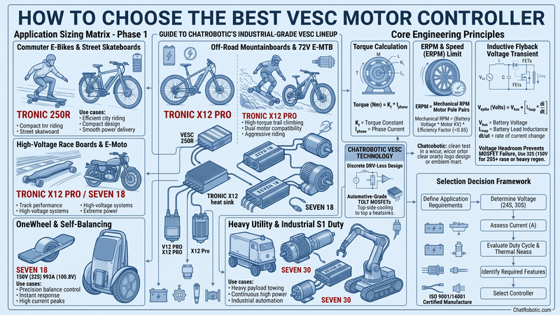
Quick VESC Sizing Matrix (Direct Selection Framework)
If you already know your system voltage and target motor phase current, use this direct selection rule:
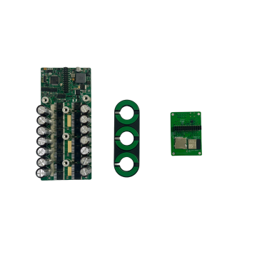
•Commuter E-Bikes & Lightweight Skateboards (10S–20S, < 3kW): Choose TRONIC 250R 125V (27S) (300A Peak). Compact, DRV-less, integrated BLE/USB-C.
•Off-Road Mountainboards & 72V E-MTBs (12S–20S, 4kW–8kW): Choose TRONIC X12 PRO 26S (662A Peak). CNC heatsink, dual CAN sync, direct IMU.
•High-Voltage Race Boards & Light E-Motorcycles (20S–32S, up to 134.4V): Choose TRONIC X12 PRO 32S (380A Peak) or SEVEN 18 32S (792A Peak). 150V MOSFETs for high-speed regen safety.
•Onewheels & Self-Balancing Boards (18S–26S, Zero Nosedive Tolerance): Choose SEVEN 18 120V (26S) 993A Peak. Instantaneous 1000A anti-nosedive current headroom with onboard low-noise IMU.
•Heavy Electric Utility Tugs, Golf Carts & Marine Propulsion (72V–96V S1 Duty): Choose SEVEN 30 (150V (32S) 950A Peak / 665A Continuous). 30-MOSFET industrial power array.
Core Engineering Rules for Choosing a VESC
Sizing a motor controller is an exact mathematical calculation. Below are the three fundamental electrical relationships every builder must calculate before purchasing hardware.
1. Motor Torque Calculation:
Torque (Nm) = K_t * I_phase
Where K_t is the motor torque constant (Nm/A) and I_phase is the Phase Current.
2. Electrical RPM (ERPM) Limit:
ERPM = Mechanical RPM * Motor Pole Pairs
Where Mechanical RPM = (Battery Voltage * Motor KV) * Efficiency Factor (~0.85).
3. Inductive Flyback Voltage Transient:
V_spike (Volts) = V_bus + [L_loop * (di/dt)]
Where V_bus is battery pack voltage and L_loop is the battery lead inductance.
Key Engineering Takeaways:
•Phase Current Determines Acceleration and Hill-Climbing Torque: Battery current dictates how much energy leaves the pack, but phase current determines actual motor shaft torque at low speeds. Your VESC peak phase current rating must be 3 to 5 times higher than the pack continuous discharge rating to deliver instant torque.
•Voltage Headroom Prevents MOSFET Punch-Through: When braking aggressively at high speeds, regenerative flyback currents create transient voltage spikes (
di/dt). A 20S battery charges to 84.0V, but inductive spikes can easily exceed 95V. You must select silicon with sufficient V_ds headroom (100V MOSFETs for <= 20S; 150V MOSFETs for 20S–32S).•ERPM Tracking Bandwidth: Ensure that your motor KV multiplied by pole pairs and maximum pack voltage stays safely within the MCU’s FOC observer tracking limit (typically 150,000 to 200,000 ERPM for modern STM32 architectures).
Step 1: Matching VESC to Drivetrain Architecture
Drivetrain topology determines whether you need single-channel control, synchronized dual CAN channels, or integrated attitude sensors.
1. Electric Skateboards & Mountainboards
•Topology: Dual independent brushless outrunners (e.g., dual 6374, 6384, or 7090 motors) communicating over a high-speed CAN bus.
•Recommended Hardware:
•High-Power All-Terrain: Dual TRONIC X12 PRO 120V (26S) 662A providing 1,324A combined peak phase current.
•Lightweight Street: Dual TRONIC 250R 125V (27S) 300A for compact 12S–16S street carving builds.
•Reference: Read our DIY Electric Skateboard Build Guide.
2. Electric Bikes, Cargo E-Bikes & High-Power E-MTB
•Topology: Single mid-drive motor (e.g., CYC, Bafang) or direct-drive hub motor (3kW–8kW peak) requiring 5V analog ADC throttle inputs and brake cutoffs.
•Recommended Hardware:
•TRONIC 250R 125V (27S) 300A for 500W–3000W commuter setups.
•TRONIC X12 PRO 120V (26S) 662A for 72V (20S) hardtail e-MTBs and Sur-Ron/Talaria light builds.
3. Onewheels & Self-Balancing Platforms
•Topology: Single high-torque direct-drive hub motor. Safety requires ultra-fast attitude PID loops (1kHz+) and massive instantaneous phase current to prevent nosedives over bumps or sudden acceleration.
•Recommended Hardware:
•SEVEN 18 120V (26S) 993A (with Case & Integrated IMU) — delivers unmatched sub-millisecond dynamic recovery.
•TRONIC X12 PRO 26S for balanced weight and power.
•Reference: Review our Onewheel VESC Upgrade Guide.
4. Autonomous Mobile Robots (AMR), AGVs & Tracked Rovers
•Topology: 2-wheel skid steer or 4-wheel independent hub drivetrains operating from 24V to 48V, controlled by an industrial PC or ROS via CAN bus or UART.
•Recommended Hardware: Daisy-chained TRONIC 250R 125V (27S) 300A units via CAN bus.
5. Electric Motorcycles, Golf Carts & Heavy Traction
•Topology: High-voltage 72V to 96V nominal systems (20S–32S Li-ion or 26S–32S LiFePO4, up to 134.4V peak) running continuous heavy load cycles (S1 continuous duty).
•Recommended Hardware:
•SEVEN 18 150V (32S) 792A for vintage e-motorcycles.
•SEVEN 30 150V (32S) 950A for golf cart repowers and commercial utility tugs.
Step 2: Sizing Voltage and Phase Current Ratings
26S vs 32S Voltage Architecture
•26S Architecture (Max 109.2V DC): Built with 100V breakdown MOSFETs offering ultra-low internal resistance (
R_ds(on)). Designed for 8S through 20S packs (up to 84.0V charged). Perfect for standard commuter and off-road PEVs.•32S Architecture (Max 134.4V DC): Built with 150V breakdown MOSFETs and 160V-tolerant auxiliary DC-DC power stages. Essential for 20S race configurations (where heavy regen braking can push bus voltage above 95V) and 22S–32S systems (92.4V to 134.4V max).
ChatRobotic Hardware Comparison Matrix
| Model Tier | Max Voltage Rating | Peak Phase Current | Continuous Phase Current | Core MOSFET Stage | Primary Build Match |
| TRONIC 250R 125V (27S) | 10S–27S (113.4V) | 300A | 210A | Discrete DRV-less | E-bikes, AGVs, Commuter Skates |
| TRONIC X12 PRO 120V (26S) | 10S–26S (109.2V) | 662A | 463A | 12x Infineon TOLT | Mountainboards, 8kW E-MTB |
| TRONIC X12 PRO 150V (32S) | 10S–32S (134.4V) | 380A | 266A | 150V Race Stage | 20S Race Skates, Light E-Motos |
| SEVEN 18 120V (26S) | 10S–26S (109.2V) | 993A | 695A | 18x Infineon TOLT | Onewheel Upgrades, Extreme PEVs |
| SEVEN 18 150V (32S) | 10S–32S (134.4V) | 792A | 554A | 18x 150V TOLT | 22S–32S E-Motorcycles |
| SEVEN 30 150V (32S) | 10S–32S (134.4V) | 950A | 400A+ Sustained | 30x Industrial Array | 96V Golf Carts, Utility Tugs |
Step 3: Evaluating Thermal Dissipation and Build Quality
MOSFET Conduction Loss Calculation:
P_loss (Watts) = 3 * (I_phase_rms)^2 * R_ds(on)
As phase current increases, heat dissipation increases with the square of the current. Selecting a controller with superior thermal packaging is non-negotiable for sustained performance.
•Infineon TOLT Top-Side Cooled MOSFETs: ChatRobotic controllers use automotive-grade TOLT packages that route heat directly through the metal top plate into a CNC aluminum heatsink, completely bypassing thermal bottlenecks in the PCB substrate.
•Discrete DRV-Less Gate Driver Architecture: Traditional hobby ESCs utilize integrated DRV8301/8302 gate driver chips that frequently burn out during high-voltage spikes. ChatRobotic uses discrete gate-drive circuitry with isolated power rails, drastically improving durability.
•Chassis Conduction Cooling: For continuous operation at maximum rated power, controllers must be mounted to an external aluminum chassis or finned heatsink using high-conductivity thermal gap pads (rated >= 6.0 W/m·K). Set soft thermal throttling at 75°C and hard cutoff at 95°C inside VESC Tool.
Detailed Model Breakdown: What to Buy
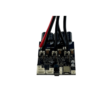
1. TRONIC 250R 125V (27S) (300A Peak) — High-Value All-Rounder
•Target: 500W to 3000W electric bikes, 12S street skateboards, autonomous rovers.
•Key Specs: 10S–27S (113.4V max), 300A peak phase, Type-C USB, integrated BLE, 5V-tolerant ADC throttle input.
•Why Choose It: Exceptional cost-to-performance ratio in an ultra-compact package with no fragile DRV chip.
•Link: TRONIC 250R 125V (27S) Product Page | TRONIC 250R In-Depth Review
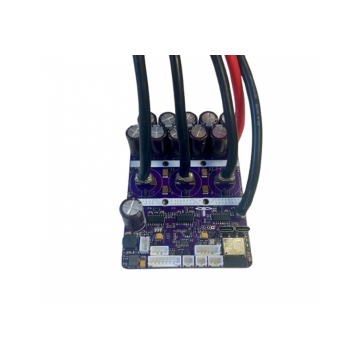
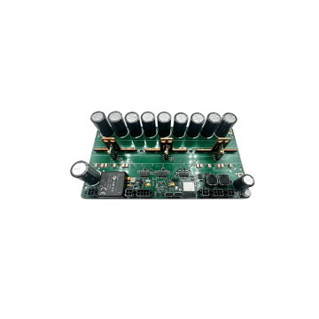
2. TRONIC X12 PRO Series (120V (26S) 662A / 150V (32S) 380A) — Performance Workhorse
•Target: Dual-motor off-road mountainboards, 72V 8kW e-MTBs, tracked exploration robots.
•Key Specs: 12× Infineon TOLT MOSFETs, integrated CNC aluminum enclosure, direct SPI IMU, dual CAN sync ports.
•Why Choose It: Perfect balance of high peak current, structural durability, and split-enclosure packaging flexibility.
•Link: TRONIC X12 PRO 26S Product Page | TRONIC X12 PRO 26S vs 32S Review
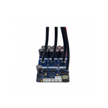
3. SEVEN 18 Series (120V (26S) 993A / 150V (32S) 792A) — Maximum Power Density
•Target: Custom Onewheel conversions, hyper-performance PEVs, lightweight electric motorcycles.
•Key Specs: 18× Infineon TOLT MOSFETs, 993A peak phase capability, direct-bus 6-axis low-noise IMU, heavy copper busbars.
•Why Choose It: The gold standard for self-balancing systems where a transient torque sag means a nosedive.
•Link: SEVEN 18 26S Product Page | SEVEN 18 Technical Review
4. SEVEN 30 150V (32S) 950A — Industrial Heavy-Duty Flagship
•Target: Commercial golf cart repowers, 96V electric utility tugs, high-torque industrial winches, marine propulsion.
•Key Specs: 10S–32S (134.4V max), 950A peak phase, 665A continuous current, massive thermal mass with heavy-duty screw terminals.
•Why Choose It: Built for sustained multi-kilowatt S1 continuous duty cycles where smaller PEV controllers overheat.
Frequently Asked Questions (FAQ)
What is the difference between Phase Current and Battery Current in VESC Tool?
Battery current represents the total DC power drawn from your battery pack (Power = V_battery * I_battery). Phase current is the AC current flowing through the motor stator windings (Torque = K_t * I_phase). At low speeds, phase current can be several times higher than battery current. Always configure your phase current limit according to the motor's thermal and saturation limits.
Can I run a 26S-rated VESC on a 26S battery pack?
While mathematically a 26S Li-ion pack reaches 109.2V (26 * 4.2V), running at the absolute voltage ceiling leaves zero margin for regenerative braking flyback spikes. For 26S or higher battery packs (up to 134.4V), you should choose a 32S-rated controller (such as the TRONIC X12 PRO 32S or SEVEN 18 32S) equipped with 150V MOSFETs.
Why is a DRV-less architecture more reliable?
Traditional VESC designs use an integrated gate driver IC (such as the DRV8301). These chips are sensitive to inductive voltage transients and ground bounce, making them the most common point of failure. A discrete DRV-less architecture separates the gate driving stages, level shifters, and power supply rails, eliminating single-point catastrophic failure.
What is MTPA and Field Weakening in VESC firmware?
•MTPA (Maximum Torque Per Ampere): Optimizes the stator current angle for interior permanent magnet (IPM) motors, maximizing torque output per amp.
•Field Weakening: Injects negative d-axis current to counteract the motor's back-EMF, allowing the motor to spin past its base mechanical RPM limit at the expense of higher phase current and lower efficiency.
Final 5-Step Selection Summary
1. Define Motor Architecture: Single motor, synchronized Dual CAN, or 4WD Multi-drop.
2. Verify Peak Voltage: Choose 26S models for <= 84.0V (up to 20S standard); choose 32S models for 20S race regen or 22S–32S (up to 134.4V max).
3. Calculate Required Peak Phase Current: 300A for light commuter builds; 662A–993A for off-road mountainboards, Onewheels, and heavy rovers.
4. Confirm Continuous Duty Cycle: Standard PEV intermittent duty (TRONIC / SEVEN 18) vs Continuous S1 industrial towing (SEVEN 30).
5. Check Sensor Requirements: Onboard 6-axis IMU for self-balancing; 5V ADC for e-bike throttles; isolated CAN for robotics.
Equip your build with commercial-grade reliability. Browse the complete ChatRobotic VESC Motor Controller Catalog or contact our powertrain engineering team for custom volume OEM/ODM integrations and 3D CAD/STEP models.


{{ commentCount }} Comments