
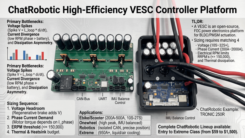
Quick Takeaway (TL;DR): A VESC (Vedder Electronic Speed Controller) is an open-source, Field-Oriented Control (FOC) power electronics platform designed for high-efficiency BLDC and PMSM motor actuation. Sizing a VESC controller requires matching four electrical and mechanical boundaries: battery voltage headroom (10S–32S+), continuous vs. peak phase current (200A–2000A), electrical RPM limits (ERPM = Mechanical RPM × Pole Pairs <= 150,000), and switching thermal dissipation. Advanced architectures leverage low R_ds(on) automotive MOSFETs, CAN-Bus multi-node telemetry, and integrated IMU balance control.
1. Technical Fundamentals and Core Engineering Bottlenecks
Selecting a motor controller for electric mobility, industrial robotics, or unmanned systems involves complex power conversion tradeoffs. Unlike standard closed-source Electronic Speed Controllers (ESCs) that use hardcoded trapezoidal (six-step) commutation, a VESC controller operates on real-time Field-Oriented Control (FOC). FOC decomposes 3-phase stator currents into torque-producing (I_q) and flux-producing (I_d) orthogonal vectors, maximizing torque-per-ampere (MTPA) while reducing acoustic noise and harmonic thermal losses.
Power engineers face three primary hardware bottlenecks during implementation:
•Voltage Transients and Inductive Spikes: Long battery lead wires introduce parasitic loop inductance (L_loop). Rapid MOSFET switching (di/dt) generates high-voltage inductive spikes: Spike Voltage (V) = L_loop × (di/dt) Without adequate bus capacitance and proper S-rating headroom, transient overshoot punches through the MOSFET gate-to-source oxide layer, leading to catastrophic failure. For root-cause diagnostics and preventative board designs, refer to our detailed technical teardown on VESC overvoltage damage.
•Phase Current vs. Battery Current Divergence: At low motor RPM and high throttle demand, motor phase current can be 3 to 5 times higher than battery bus current. Sizing power stages based solely on battery pack ratings frequently causes thermal saturation of phase bridges. See the exact conversion math in our guide on battery current vs phase current.
•Thermal Dissipation Asymmetry: High-current switching operations (20 kHz to 50 kHz) generate severe conduction and switching losses in compact enclosures. Efficient heat extraction from the MOSFET silicon junction (T_j) to the ambient heatsink (T_a) is the primary limiting factor for continuous current capability.
2. Core Electrical Architecture and Parameter Sizing
•System Sizing Sequence:
•Step 1: Battery Voltage & Safety Headroom Verification
•Step 2: Motor Phase Current Demand (RMS & Peak)
•Step 3: ERPM Commutation Threshold Calculation
•Step 4: Thermal Loss & Chassis Heatsink Budget
Voltage Sizing and Bus Margins (S-Rating)
Lithium cell configurations dictate nominal and peak bus voltages. Because regenerative braking elevates DC bus voltage above static pack levels, controllers must maintain an absolute minimum safety margin of 15% to 20% below maximum Silicon breakdown ratings (V_ds_max).
•12S–14S (50.4V–58.8V peak): Standard for kick scooters, light AGVs, and sub-1kW robotics.
•18S–26S (75.6V–109.2V peak): Standard for high-performance eskate, EUC, light EVs, and delivery rovers.
•26S–32S+ (109.2V–140.0V+ peak): Ultra-high-power platforms, eVTOL sub-systems, electric motorcycles, and heavy robotic traction.
Phase Current and Conduction Loss Sizing
Motor torque generation directly depends on phase current (I_phase), not input battery current (I_bat). Power stage MOSFET conduction loss is governed by:
Conduction Loss (W) = 3 × (I_rms)^2 × R_ds(on)
Where:
•I_rms is the continuous root-mean-square phase current.
•R_ds(on) is the static drain-to-source on-resistance at operating junction temperature (T_j ≈ 100°C to 125°C).
When sizing for acceleration or sustained hill climbs, calculate power loss using maximum junction temperature resistance (R_ds(on) typically increases by 1.5× to 1.8× compared to 25°C room ratings).
ERPM Limits and High-Speed Commutation
The microcontroller unit (MCU) executing the VESC FOC observer loop requires adequate clock cycles to sample current shunts and compute vector transformations. Electrical RPM (ERPM) defines commutation frequency:
ERPM = Mechanical RPM × Motor Pole Pairs
Exceeding the hardware ERPM processing threshold (typically 100,000 to 150,000 ERPM on standard platforms) results in observer desynchronization, loss of commutation angle, overcurrent faults (ABS_OVERCURRENT), and potential power-stage shoot-through.
Connectivity and Control Interfaces
•CAN-Bus: Multi-node synchronization across multi-drive configurations (dual-hub, 4WD robotic rovers) with microsecond latency.
•UART: High-throughput bidirectional telemetry stream to companion microcontrollers (ESP32, Raspberry Pi, ROS compute modules).
•ADC / PPM / UART: Analog and digital throttle inputs with internal pull-down and noise filtering.
•Digital Encoders / Hall Sensors: ABI, AS5047, or Hall inputs providing zero-RPM absolute position detection for load holding and high-precision torque-vectoring robotics.
3. VESC Controller Types by Current Class & Selection Benchmarks
To select the appropriate hardware class, electrical designers must evaluate current handling, voltage boundaries, structural packaging, and active thermal management across the ChatRobotic VESC Motor Controllers catalog.
| Class | Typical Current | Best For | ChatRobotic Example | Engineering Impact |
| Light-Duty | 200A–500A | Ebikes, kick scooters, light robotics, AGV | TRONIC 250R 125V (27S) 300A — 210A continuous | Compact 84 × 72 × 28 mm footprint with USB-C tuning, covering 10S–27S (40V–125V) mobility platforms. |
| Performance | 266A–662A | Eskate, EUC, small EVs, go-karts | TRONIC X12 PRO 120V (26S) 662A · 150V (32S) 380A | High burst phase current in a 95 × 73 × 22 mm top-side-cooled TOLT stage with 6-axis IMU and Bluetooth. |
| Extreme-Duty | 950A–2376A | E-motorcycles, industrial/agri drives, research | SEVEN 30 120V (26S) 1655A · 150V (32S) 950A, TRONIC X54 150V (32S) 1710A, SEVEN54 V2 150V (32S) 2376A | 30- and 54-device MOSFET arrays engineered for extreme torque demands without thermal throttling. |
| Entry / Sub-100V | 210A–300A | Kick scooters, light e-bikes, small AGVs, 8S–21S packs | VESC-S 90V (21S) 300A V2, VESC-LS 57V (14S) 300A V4 | Lowest-cost route into open-source FOC, from $59 — ideal for sub-90V packs and dual-drive light EVs. |
| Compact High-Density | 993A (26S) / 792A (32S) | Onewheel, robots, heavy-duty EV | SEVEN 18 120V (26S) 993A · 150V (32S) 792A | Maximum power density per cubic centimetre (145 × 65 × 30 mm) with hybrid nylon/aluminium thermal enclosure. |
Complete ChatRobotic VESC Hardware Lineup
Engineers and system integrators can explore and source specific voltage and current configurations directly. All models below are DRV-less, 2-board builds with ×3 copper (4× DC-link copper weight), USB-C programming, integrated 6-axis IMU, Bluetooth, CAN bus, latching-switch ON/OFF, thermal-sensor extension, and soft/hard thermal limiting.
| Model | Max Input | Battery Range | Continuous | Peak (10 s) | MOSFET Array | Size / Weight | Price |
| TRONIC 250R 125V (27S) 300A | 125V | 10S–27S | 210A | 300A | 6× HY5012W | 84 × 72 × 28 mm / 0.40 kg | $150 |
| TRONIC X12 PRO 120V (26S) 662A | 120V | 10S–26S | 463A | 662A | 12× IPTC017N12NM6ATMA1 | 95 × 73 × 22 mm / 0.40 kg | $299 |
| TRONIC X12 PRO 150V (32S) 380A | 150V | 10S–32S | 266A | 380A | 12× IPT039N15N5ATMA1 | 95 × 73 × 22 mm / 0.40 kg | $299 |
| SEVEN 18 120V (26S) 993A | 120V | 10S–26S | 695A | 993A | 18× IPTC017N12NM6ATMA1 | 145 × 65 × 30 mm / 0.40 kg | $450 |
| SEVEN 18 120V (26S) 993A With Case | 120V | 10S–26S | 695A | 993A | 18× IPTC017N12NM6ATMA1 | 145 × 65 × 30 mm (external) / 0.70 kg | $550 |
| SEVEN 18 150V (32S) 792A | 150V | 10S–32S | 554A | 792A | 18× IPTG025N15NM6ATMA1 | 145 × 65 × 30 mm / 0.40 kg | $450 |
| TRONIC 1000 150V (32S) 1000A | 150V | 10S–32S | 700A | 1000A | 36× IRFP4568PBF (TO-247AC-3) | 220 × 115 × 40 mm / 1.20 kg | $399 |
| SEVEN 30 120V (26S) 1655A | 120V | 10S–26S | 1158A | 1655A | 30× IPTC017N12NM6ATMA1 | 190 × 90 × 40 mm / 0.60 kg | $750 |
| SEVEN 30 150V (32S) 950A | 150V | 10S–32S | 665A | 950A | 30-device industrial array | 190 × 90 × 40 mm / 0.60 kg | $750 |
| TRONIC X54 150V (32S) 1710A | 150V | 10S–32S | 1197A | 1710A | 54× IPT039N15N5ATMA1 | — / 0.40 kg | $1,100 |
| SEVEN54 V2 150V (32S) 1710A | 150V | 10S–32S | 1197A | 1710A | 54× IPT039N15N5ATMA1 | 190 × 120 × 24 mm / 0.40 kg | $1,350 |
| SEVEN54 V2 150V (32S) 2376A | 150V | 10S–32S | 1663A | 2376A | 54× IPTG025N15NM6ATMA1 | 190 × 120 × 24 mm / 0.40 kg | $1,500 |
Every model shares a 40V (10S) minimum operating voltage. Continuous figures assume adequate cooling — liquid cooling or direct chassis conduction. Prices and stock verified against ChatRobotic factory listings; confirm at purchase.
Sub-100V & Entry-Level Controllers
For builds that never exceed a 21S pack, the full-size 120V/150V platforms are over-specified. These compact boards cover 8S–21S at a fraction of the cost:
| Model | Max Input | Battery Range | Continuous | Peak (10 s) | MOSFET Array | Size / Weight | Price |
| VESC-LS 57V (14S) 300A V4 | 57V | 9S–14S | 210A | 300A | 6× IPT015N10N5 | 95 × 50 × 23 mm / 0.30 kg | $59 |
| VESC-LS 57V (14S) 300A Dual Motor V4 | 57V | 9S–14S | 210A | 300A | 12× IPT015N10N5 | 0.40 kg | $99 |
| VESC-S 90V (21S) 300A V2 | 90V | 8S–21S | 210A | 300A | 6× IPT015N10N5 | 90 × 60 × 25 mm / 0.30 kg | $69 |
The Dual Motor V4 integrates two independent 300A channels on one PCB, making it the cheapest route to a synchronized dual-drive scooter, skid-steer robot, or light e-bike without running a CAN link between two separate controllers.
Enclosures & Accessories
| Item | Purpose | Price |
| SEVEN 18 Enclosure – Nylon Top, Aluminum Base | Retrofit housing for an existing bare SEVEN 18 board (controller not included) | $100 |
| VESC CAN Bus Bluetooth Module | 36 × 21 mm add-on for wireless telemetry and mobile VESC Tool access over the CAN bus | $19 |
Pre-Fitted Enclosure Variants (Nylon Top / Aluminium Base)
Where a build needs environmental sealing and structural protection out of the box, the SEVEN 18 and TRONIC X12 PRO lines ship in a machined nylon-top / aluminium-base housing. Electrical ratings are identical to the bare boards; only the external dimensions, weight, and price change.
| Model | Max Input | Continuous | Peak (10 s) | External Size / Weight | Price |
| TRONIC X12 PRO 120V (26S) 662A With Case | 120V | 463A | 662A | 95 × 73 × 22 mm / 0.80 kg | $399 |
| TRONIC X12 PRO 150V (32S) 380A With Case | 150V | 266A | 380A | 95 × 73 × 22 mm / 0.80 kg | $399 |
| SEVEN 18 120V (26S) 993A With Case | 120V | 695A | 993A | 145 × 65 × 30 mm / 0.70 kg | $550 |
| SEVEN 18 150V (32S) 792A With Case | 150V | 554A | 792A | 145 × 65 × 30 mm / 0.70 kg | $550 |
The aluminium baseplate doubles as the primary thermal path — mount it directly against the vehicle subframe with a ≥ 6.0 W/m·K gap pad, or add a liquid chill plate for sustained high-current duty.
For full architectural teardowns and build integration guides, review our SEVEN 18 VESC review, specs & build guide.
4. Application Matching and Step-by-Step Commissioning
•Powertrain Application Matrix:
•Ebike / Scooter: 200A–500A class, 10S–27S support, PAS (Pedal Assist Sensor) or ADC hall throttle input. Sub-90V city builds can drop to the 300A VESC-S / VESC-LS class.
•Electric Skateboard: Dual VESC synchronization via CAN bus, 1000A-class burst current for steep hill climbs.
•EUC / Onewheel: Built-in 6-axis IMU balance control, high instantaneous peak current, compact sealed enclosure.
•Robotics / AGV: Isolated CAN bus, precision position control, ROS node integration, custom telemetry scripting.
•Industrial / E-Motorcycle: 950A–2376A extreme-duty class, billet CNC enclosure, active liquid or forced-air cooling.
Engineering Commissioning Checklist
1. Polarity Check: Verify battery pack polarity using a digital multimeter before mating primary connectors.
2. Current-Limited Power Up: Power up initially using a current-limited DC bench power supply (set to pack nominal voltage, 1.0A limit) or an anti-spark connector with integrated pre-charge resistors.
3. Firmware Connection: Establish connection via USB/UART in VESC Tool. Refer to Benjamin Vedder's open-source VESC firmware for base control loop references.
4. FOC Motor Detection: Navigate to the FOC Motor Setup Wizard. Measure stator resistance (R), stator inductance (L), and flux linkage (Lambda) under zero-load conditions.
5. Thermal Cutoff Configuration: Set
MOSFET Temp Cutoff Startto 80°C andMOSFET Temp Cutoff Endto 95°C. This linear rollback prevents catastrophic junction breakdown during prolonged full-throttle duty cycles.6. Input Mapping: Calibrate ADC throttle input voltages, set a 5% deadband, and tune throttle ramp times (0.15s–0.30s) to prevent inductive bus surges during rapid trigger releases. Additional application notes can be found across the ChatRobotic Powertrain Knowledge Base.
Common Mistakes to Avoid
•Undersizing Phase Current: Sizing by battery current rather than motor phase demand causes premature thermal rollback and lost low-end torque.
•Exceeding Maximum Input Voltage: Connecting a fully charged pack above rated Silicon V_ds leads to instant MOSFET puncture.
•Ignoring ERPM Limits: Running high-KV motors on high-voltage packs past 150,000 ERPM leads to observer desynchronization and ABS_OVERCURRENT faults.
•Neglecting Thermal Sinks: Operating above 200A phase current without direct chassis conduction or active airflow induces rapid thermal throttling.
•Improper Throttle Grounding: Sharing throttle analog ground with high-current power ground introduces signal noise and unintended throttle spikes.
5. System Integration and ChatRobotic Engineering Solutions
Scaling high-power electronic drive systems from prototyping to volume manufacturing introduces complex supply chain and integration challenges. ChatRobotic addresses these bottlenecks by providing integrated power electronics and motor subsystems:
•TRONIC Series: Ruggedized controllers engineered for harsh, high-vibration off-road, maritime, and robotic deployments.
•SEVEN Series: Ultra-compact, high-power-density controllers featuring integrated balance IMUs and advanced thermal packaging.
•Turnkey Motor Integration: Native compatibility with LandDrive (robotics/e-mobility), AirDrive (heavy-lift drones/eVTOL), and SeaDrive (marine propulsion) high-torque motors.
•OEM/ODM & NDAA-Compliant PCBA: ChatRobotic provides full NDAA-compliant hardware architectures, custom firmware branch maintenance, CNC enclosure machining, and ISO 9001 / ISO 14001 certified volume manufacturing.
Frequently Asked Questions (FAQs)
Q1: What is the primary difference between a VESC and a standard RC ESC?
A: A standard ESC operates as a closed black box with fixed trapezoidal commutation and basic throttle response. A VESC runs open-source Field-Oriented Control (FOC) firmware, allowing full parameter tuning (phase current, field weakening, regenerative braking curves, thermal rollback), real-time bidirectional telemetry, and multi-node CAN synchronization.
Q2: How do I size continuous vs. peak current for my powertrain?
A: Match the controller's continuous current rating to the motor's continuous thermal rating during sustained operation. Size peak current (10-second burst) to handle maximum acceleration, hill climb launch torque, or heavy obstacle traversal. Always maintain at least a 20% to 30% current safety headroom above expected peak operational loads.
Q3: Can ChatRobotic VESC controllers be customized for OEM and industrial applications?
A: Yes. ChatRobotic operates ISO9001/14001 certified manufacturing facilities, providing custom PCB layouts, customized CNC billet enclosures, NDAA-compliant component sourcing, application-specific firmware adaptations, and custom CAN communication protocols for commercial robotics, e-mobility, and defense applications.
Q4: Is VESC Tool free to use for configuration and telemetry?
A: Yes. VESC Tool is free, open-source software available for desktop (Windows, macOS, Linux) and mobile (Android, iOS) platforms, used for initial FOC motor detection, parameter tuning, firmware updates, and real-time data logging.
Q5: What does ERPM mean and how does it limit motor selection?
A: ERPM is Electrical RPM, calculated as Mechanical RPM multiplied by the motor's pole pairs. Standard microcontroller architectures cap processing at approximately 150,000 ERPM. If a high-KV motor running on high voltage exceeds this threshold, the controller will lose commutation lock and trigger an overcurrent fault.
Need Custom High-Power Powertrain Engineering?
Explore the complete ChatRobotic VESC Motor Controllers catalog, or get in touch with our engineering and hardware manufacturing team directly for custom CAD/STEP models, specialized 26S–32S+ power stages, and volume OEM/ODM inquiries: Contact ChatRobotic Engineering


{{ commentCount }} Comments