
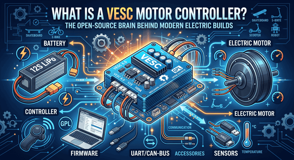
Quick Takeaway (TL;DR): A VESC (Vedder Electronic Speed Controller) is an open-source, programmable power electronics platform designed for brushless DC (BLDC) and permanent magnet synchronous motors (PMSM). Operating on real-time Field-Oriented Control (FOC), a VESC mathematically aligns stator current vectors with rotor flux to maximize torque-per-ampere, eliminate acoustic noise, and enable bidirectional regenerative braking. Advanced implementations scale from 26S (109.2V) to 32S+ (134.4V–140V) with phase current handling from 200A to 2000A.
1. Technical Definition & Working Principles of VESC
Created by Benjamin Vedder and released under the open-source GPL v3 license, a VESC controller is not merely a speed regulator—it is a fully configurable motion control computer. Standard hobby Electronic Speed Controllers (ESCs) treat motor commutation as a fixed-sequence black box, whereas a VESC executes continuous vector calculations to regulate torque, velocity, and rotor position in real time.
VESC Control & Signal Processing Architecture:
•Digital Control & Processing Core
•STM32 Microcontroller executing FOC observer algorithms (20 kHz–50 kHz loop)
•Multi-Protocol Interfaces: Isolated CAN Bus, UART, SPI, I2C, USB-C
•Analog Sensing: Dual/Triple Phase Shunts, DC Bus Voltage Dividers, NTC Thermistors
•Inertial Tracking: Onboard 6-Axis IMU (Attitude / Balance Angle Computation)
•Gate Drive & Power Inverter Stage
•Discrete or Integrated Gate Drivers with Desaturation / Shoot-Through Protection
•3-Phase Half-Bridge Inverter Array (6 to 18 Automotive MOSFETs)
•Low-Inductance DC-Link Decoupling Capacitors
•Actuation & Telemetry Output
•3-Phase Sinusoidal Motor Terminals (Smooth FOC Commutation)
•High-Throughput Live Telemetry (Current, RPM, Voltage, Amp-Hours, Temperatures)
Field-Oriented Control (FOC) Execution
The core advantage of a VESC controller is its digital signal processing pipeline:
•Clarke & Park Transforms: The microcontroller samples two or three stator phase currents and translates 3-phase AC coordinates into a 2-axis rotating reference frame:
•Direct Axis Current (I_d): Regulates rotor magnetic flux (set to zero for non-salient motors, or driven negative for field weakening at high RPM).
•Quadrature Axis Current (I_q): Directly generates mechanical output torque: Torque (Nm) = 1.5 × Pole Pairs × Lambda_m × I_q
•Space Vector PWM (SVPWM): Reconstructs sinusoidal phase voltages at switching frequencies between 20 kHz and 50 kHz, maximizing DC bus voltage utilization while minimizing harmonic heating.
•Sensorless Flux Observer: Tracks rotor position via back-EMF integration when physical Hall sensors or absolute encoders are not present, enabling reliable sensorless operation across wide speed ranges.
If you are beginning an electrification project and need to size voltage, phase current, and ERPM boundaries, consult our complete 2026 VESC buyer's guide.
2. VESC vs. Standard ESC: Core Architectural Differences
Standard RC and generic industrial ESCs rely on six-step trapezoidal commutation. This square-wave switching energizes only two phase windings at any given instant, causing significant torque ripple, acoustic whine, and switching energy losses.
| Feature / Metric | Standard Open-Loop ESC | Commercial VESC Motor Controller | Engineering Impact |
| Commutation Method | 6-Step Trapezoidal (Block) | Field-Oriented Control (FOC) | Smooth, silent rotation with maximized torque-per-ampere efficiency. |
| Firmware Architecture | Closed, static, proprietary | Open-source (GPL v3), fully auditable | No vendor lock-in; supports custom algorithms and continuous firmware upgrades. |
| Current Regulation | Duty-cycle throttle control | True closed-loop phase & battery current control | Direct torque demand control with precise acceleration and braking ramps. |
| Regenerative Braking | Dissipative dynamic braking or absent | Fully programmable bidirectional regen | Captures kinetic energy back into the battery pack while preserving mechanical brakes. |
| Position Sensing | Sensorless or basic 60°/120° Hall | Hall, ABI Encoder, AS5047, BiSS, Sensorless | Zero-RPM torque hold, index homing, and precision robotic trajectory tracking. |
| Multi-Node Sync | PWM Y-cables (Unsynchronized) | Microsecond-latency isolated CAN Bus | Synchronized electronic differential control and multi-axis robotics coordination. |
| Telemetry & Diagnostics | None or basic beep codes | Live streaming via USB-C, BLE, CAN, UART | Real-time logging of MOSFET temperatures, phase currents, duty cycles, and faults. |
3. Power Electronics Hardware Tiers & Sizing Matrix
While VESC firmware provides the algorithmic brain, the physical power stage dictates the maximum electrical limits of the system. Inverter conduction loss scales quadratically with phase current:
Conduction Loss (W) = 3 × (I_rms)^2 × R_switch_eff
To prevent junction breakdown (T_j > 150°C), commercial VESC designs utilize automotive-grade MOSFET packages, discrete driver stages, and heavy-copper PCB layouts.
Hardware Selection Framework:
•Light Utility & Urban Mobility (1kW–5kW)
•Target Voltage: 10S–26S (up to 109.2V) | Continuous Current: 50A–150A
•Hardware Architecture: Discrete DRV-Less Power Stage
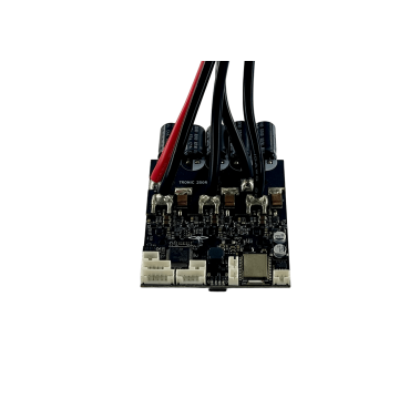
•Reference Solution: TRONIC 250R 125V (27S) 300A
•Performance Drives & Self-Balancing (5kW–25kW)
•Target Voltage: 18S–32S (up to 134.4V) | Continuous Current: 150A–450A
•Hardware Architecture: Infineon TOLT Top-Side Cooled MOSFETs + Integrated IMU
•Reference Solutions: TRONIC X12 PRO / SEVEN 18
•Extreme Traction & Heavy Industry (25kW–100kW+)
•Target Voltage: 26S–32S+ (up to 140.0V+) | Continuous Current: 500A–2000A
•Hardware Architecture: Direct-FET / Heavy SMT Arrays + Liquid Cold-Plates
•Reference Solutions: SEVEN 30 / TRONIC X54 / TRONIC 1000
Commercial Hardware Lineup & Sourcing
•Accessible 26S Entry: TRONIC 250R 125V (27S) 300A – DRV-less rugged architecture with USB-C and integrated IMU. Read our TRONIC 250R review.
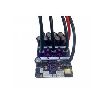
•High-Voltage Performance Workhorse: TRONIC X12 PRO 26S (662A) and TRONIC X12 PRO 32S (380A) – 12× Infineon TOLT MOSFETs with onboard ESP32-C3 BLE. Read the TRONIC X12 PRO 26S vs 32S review.
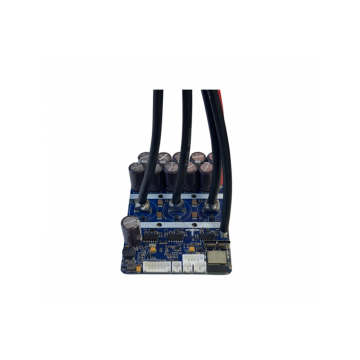
•Ultra-High Density Flagship: SEVEN 18 120V (26S) 993A With Case – Nylon Top, Aluminum Base and SEVEN 18 150V (32S) 792A – 18× Infineon TOLT MOSFETs delivering four-figure peak phase current. Read our SEVEN 18 VESC review and build guide.
•Heavy Industrial Traction: TRONIC 1000 150V (32S) 1000A and extreme 2000A-class inverters. Browse the complete ChatRobotic VESC Motor Controllers Catalog.
4. Key Application Domains & Field Implementation
Because VESC firmware separates control algorithms from hardware peripherals, a single controller model can be deployed across diverse motion platforms by reconfiguring software parameters in VESC Tool.
Motion Platform Integration:
•Electric Skateboards & Mountainboards
•Setup: Dual controllers synchronized over CAN bus with electronic traction control.
•Guide: Follow our Dual-VESC Eskate DIY Build Guide.
•Self-Balancing Systems & Onewheels
•Setup: Direct attitude tracking via onboard 6-axis IMU running ReFloat balance packages.
•Guide: Follow our VESC Onewheel Upgrade & Customization Guide.
•E-Bikes, Commuter Scooters & Light AGVs
•Setup: Linear 0–3.3V ADC Hall throttles with programmable regenerative braking ramps.
•Guide: Follow our Best VESC Controller by Application Guide.
•Autonomous Robotics & Multi-Axis Actuators
•Setup: Microsecond CAN/UART telemetry streaming to companion ROS/ROS2 compute nodes.
•Electric Skateboards (E-Skate): Dual inverters synchronized over CAN bus provide independent wheel torque vectoring. Follow our dual-VESC eskate DIY build guide.
•Self-Balancing Vehicles & Onewheels: Low-latency onboard 6-axis IMUs run pitch/roll PID loops to maintain platform equilibrium. Follow our VESC Onewheel upgrade and customization guide.
•E-Bikes & Light Electric Vehicles: Smooth throttle ramping and regenerative braking eliminate drivetrain shudder. Compare models in our best VESC controller by application guide.
•Autonomous Mobile Robots (AMRs) & AGVs: Real-time speed and position control via ROS/ROS2 nodes over CAN bus. Review the three-model VESC buyer's guide.
•Community Showcase: See 10 real-world implementations in our top 10 high-performance VESC builds.
5. VESC Tool Setup, Commissioning & ChatRobotic Turnkey OEM Capabilities
Configuring a VESC controller is handled through VESC Tool, available for Windows, macOS, Linux, Android, and iOS.
Commissioning Sequence:
•Step 1: Pre-charge Circuit Connection & Current-Limited Bench Power-Up (1.0A limit)
•Step 2: Automated FOC Motor Wizard Detection
•Stator Resistance (R) Measurement
•Stator Inductance (L) Measurement
•Motor Flux Linkage (Lambda) Determination
•Hall Sensor / Encoder Offset Calibration
•Step 3: Current & Voltage Protection Mapping
•Maximum Phase Current (Torque Ceiling)
•Maximum Battery Draw & Regenerative Braking Current
•Minimum/Maximum Battery Cutoff Voltages
•Step 4: Application I/O Configuration (ADC Throttle, CAN Bus ID, Onboard IMU Alignment)
•Step 5: Thermal Rollback Setup (75°C Start / 95°C Hard Cutoff)
To learn more about step-by-step controller selection and tuning parameters, read our comprehensive VESC selection guide.
Turnkey Powertrain Integration & ChatRobotic Engineering
Scaling drive electronics into commercial volume production requires enterprise-grade manufacturing standards, validated thermal layouts, and component traceability:
•Integrated Motor Ecosystem: Native compatibility with ChatRobotic LandDrive (traction/direct-drive), AirDrive (aerial propulsion), and SeaDrive (marine thrusters).
•NDAA-Compliant Electronic Manufacturing: Certified supply chains free of restricted telecommunications and semiconductor components, suitable for aerospace, defense, and commercial robotics contracts.
•Custom Firmware & Communication Stacks: Customized VESC firmware forks featuring proprietary CAN message sets, custom throttle curves, and industrial safety interlocks.
•Turnkey PCBA & CNC Enclosure Services: ISO9001/14001 certified rapid prototyping, high-density SMT assembly, and custom CNC billet aluminum enclosure milling.
Frequently Asked Questions (FAQs)
Q1: What does VESC stand for and who created it?
A: VESC stands for Vedder Electronic Speed Controller. It was originally developed by Swedish engineer Benjamin Vedder as an open-source, high-performance motor controller platform and is now maintained by an active global community of power electronics engineers.
Q2: What is the primary operational advantage of Field-Oriented Control (FOC)?
A: FOC decomposes 3-phase stator currents into torque-producing (I_q) and flux-producing (I_d) orthogonal vectors. By driving I_d to zero and dynamically controlling I_q with pure sinusoidal Space Vector PWM, FOC delivers maximum torque-per-ampere efficiency, eliminates motor commutation noise, and reduces harmonic thermal losses.
Q3: Can a VESC controller operate sensorless brushless motors?
A: Yes. VESC controllers incorporate advanced sensorless flux observer algorithms that estimate rotor position by tracking back-EMF integration in real time. For applications requiring zero-RPM starting torque under heavy loads (such as electric skateboards or robotic actuators), Hall sensors or absolute encoders (ABI/AS5047) can be connected.
Q4: How does regenerative braking work on a VESC controller?
A: During deceleration, the VESC operates the inverter as a boost converter, using motor phase inductance to step up the generated back-EMF voltage above the battery bus voltage. This forces reverse phase current back into the battery pack, providing controlled electric braking while recharging the battery.
Q5: How do multiple VESC controllers communicate in multi-motor drivetrains?
A: Multiple VESC controllers connect via an isolated multi-drop CAN-bus network. A designated Master controller receives primary throttle commands, executes torque vectoring calculations, and broadcasts current setpoints to Slave controllers with microsecond-level synchronization.
Related Technical Reading & Build Guides
•VESC Controller: The Complete 2026 Buyer's Guide (26S/32S, 200A–2000A)
•SEVEN 18 VESC Review — 120V (26S) 993A / 150V (32S) 792A Specs & Build Guide
•SEVEN 18 vs TRONIC X12 PRO vs TRONIC 250R — VESC Buyer's Guide
•Best VESC Controller by Application: Onewheel, Robotics, Ebike & More
Need Custom High-Power Powertrain Engineering? Explore the complete ChatRobotic VESC Motor Controllers Catalog or contact our power electronics team directly for custom 26S–32S+ power stages, CAD/STEP models, and volume OEM/ODM manufacturing: Contact ChatRobotic Engineering


{{ commentCount }} Comments