
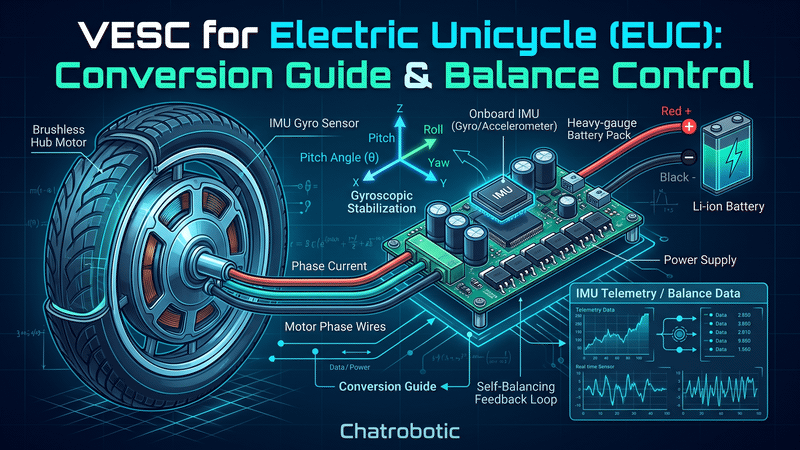
Quick Takeaway (TL;DR): Migrating an Electric Unicycle (EUC) to open-source VESC architecture eliminates proprietary current bottlenecks and protects riders from high-speed cutouts by expanding bus voltage to 100V–150V (24S–32S). Safe builds require in-line phase shunts, field-weakening calibration, DRV-less discrete gate drivers, and low-thermal-resistance heatsink coupling directly to the EUC chassis structure.
1. Technical Demands & Safety Stakes: Why EUC Riders Migrate to VESC
Unlike multi-wheeled light electric vehicles where controller failure results in unpowered coasting, an Electric Unicycle (EUC) relies strictly on continuous electromagnetic torque to balance the rider. A sudden torque interruption at 60 km/h causes an instantaneous high-speed face-plant.
Factory controllers from legacy EUC manufacturers (such as Begode, Inmotion, and Kingsong) present severe architectural limitations:
•Proprietary Current Clamping: Factory firmware imposes conservative phase current limits and restrictive thermal throttling tables. When a rider hits a steep incline, pothole, or headwind, the controller throttles torque abruptly, causing an unavoidable forward cutout.
•Voltage Margin Depletion at Speed: As vehicle speed climbs, motor back-EMF increases linearly. When back-EMF plus internal phase resistance drops approach the battery pack's nominal voltage, duty cycle saturates at 90%–95%: V_terminal = Back_EMF + (I_phase × R_phase) Once duty cycle maxes out, the controller cannot inject corrective balancing torque, precipitating a catastrophic shutdown.
•Black-Box Failures & Repair Lockouts: Proprietary boards conceal internal MOSFET operating temperatures, individual phase currents, and duty cycle telemetry. When a factory board blows, riders face supply-chain delays for replacement boards that carry the same underlying hardware design flaws.
Migrating to open-source VESC controllers provides unconstrained Field-Oriented Control (FOC), customizable pitch/roll response, transparent CAN telemetry, and access to field-weakening algorithms to safely extend top-end speed margins.
2. Electrical Architecture: Voltage Scaling, Phase Current & Field Weakening
Modern EUCs feature high-power hub motors (2,000W to 5,000W continuous, peaking past 12,000W) driven by multi-parallel high-discharge 21700 battery arrays. Selecting an inverter requires balancing continuous thermal dissipation with peak burst capacity.
Voltage Classifications in EUC Conversions
•84V Architectures (20S Li-ion / 67.2V–84.0V): Legacy platforms (e.g., Inmotion V11, Begode MSX 84V, Kingsong 16X/18XL). These builds draw higher phase amps to deliver torque, demanding low-resistance wiring.
•100.8V Architectures (24S Li-ion / 80.0V–100.8V): High-performance street and trail wheels (e.g., Begode Master, T4, Veteran Sherman 100V).
•126V–134.4V Architectures (30S–32S Li-ion / 100V–134.4V): Flagship hyper-wheels (e.g., Begode Master Pro, Veteran Patton, Lynx, Commander GT). Inverters must possess absolute maximum voltage ratings of at least 150V to safely absorb regenerative voltage spikes during aggressive braking: V_spike = V_bus + [L_bus × (di/dt)]
Field Weakening (Flux Weakening) Mechanics
When an EUC reaches high speeds, back-EMF approaches DC bus voltage. VESC firmware allows injection of a negative direct-axis current (-I_d) to oppose the permanent magnet rotor flux: V_d = R_phase × I_d - (omega_e × L_q × I_q) V_q = R_phase × I_q + [omega_e × (L_d × I_d + lambda_pm)]
By injecting -I_d, the effective magnetic flux (lambda_pm) is suppressed, lowering back-EMF and expanding operational wheel speed by 15% to 30%. However, phase current increases proportionally, amplifying motor stator heating (I_phase^2 × R), requiring conservative thermal cutoff configurations in VESC Tool.
3. Controller Sizing Matrix: Benchmarking ChatRobotic VESC Lineup for EUCs
Not every high-power controller suits the unique constraints of an EUC. Dual-channel inverters (such as the Dual VESC-LS 57V) carry redundant motor stages and inadequate voltage ceilings. An EUC requires a single-axis, high-voltage (90V–150V), ultra-high-current controller capable of fitting inside narrow lateral side fairings.
We evaluated ChatRobotic's high-power VESC portfolio to establish this EUC hardware selection benchmark:
| Controller Model | Voltage Range | Peak Current | Substrate & Gate Driver | Integrated Sensors | Recommended EUC Tier |
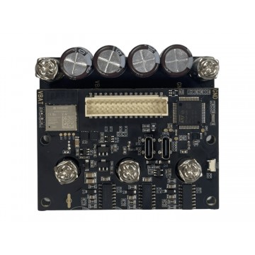
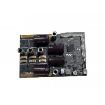
| X6 150V (32S) 171A VESC | 40V–150V (10S–32S) | 171A burst / 120A cont | DRV-less Discrete TO-247 FETs | Built-in IMU chip, Bluetooth | Best Overall Conversion Pick: 84V–134V agile trail wheels & drop-in conversions |
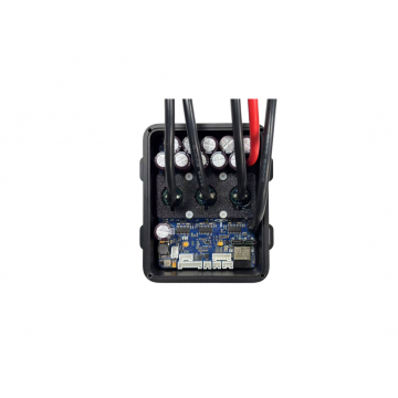
| TRONIC X12 150V (32S) 380A With Case | Up to 150V (32S) | 380A burst / 180A cont | Direct-FET on Aluminum Baseplate | Requires external IMU | Flagship Hyper-Wheel Pick: 100V–134V wheels (Master, Sherman, Lynx, Patton) |
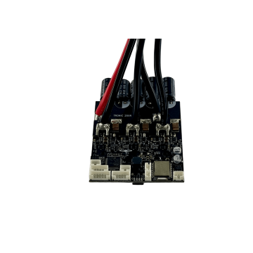
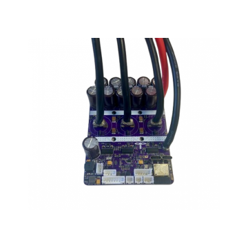
| TRONIC 250R 125V (27S) 300A VESC | Up to 125V (27S) | 300A burst / 150A cont | Heavy copper PCB, flat heatsink | Requires external IMU | Best Value Mid-Tier Pick: 100.8V (24S) platforms (Begode T4, Master v1/v2) |
| VESC-S 90V (21S) 300A V2 | Up to 90V (21S) | 300A burst / 120A cont | Direct-FET compact module | Requires external IMU | Legacy 84V (20S) Pick: Compact budget conversions (Inmotion V11, Kingsong 16X) |
| TRONIC X12 120V (26S) 662A VESC | Up to 120V (26S) | 662A burst / 250A cont | Direct-FET Aluminum IMS | Requires external IMU | Racing Track Specialist: 100V race setups requiring explosive burst acceleration |
Hardware Sizing Recommendations
•The Cleanest Balance Build: The X6 150V (32S) 171A VESC Motor Controller is the most streamlined solution for DIY EUC builders. Featuring a native built-in IMU chip, it eliminates external sensor wiring harnesses that vibrate loose during curb jumps. Its 150V ceiling provides absolute protection against overvoltage on 84V, 100V, and 126V batteries, while heavy-duty M5 screw terminals secure phase connections against high-current thermal melting.
•The Uncompromised High-Torque Build: For heavyweight riders and hyper-wheel platforms pushing 100V–134V packs, the TRONIC X12 150V (32S) 380A VESC Controller (With Case) delivers 380A of phase current headroom. Its hybrid nylon-top and aluminum-base enclosure bolts directly to structural chassis heatsinks, dissipating sustained climbing heat.
•The 100V Sweet Spot: The TRONIC 250R 125V (27S) 300A VESC Controller offers a compact, cost-effective platform for 24S (100.8V peak) systems, delivering 300A burst torque without packaging issues.
•Industrial/Extreme Notes: Larger models in the VESC (100A~3000A) portfolio—such as the SEVEN 18 (993A) and SEVEN 30 (1655A)—are engineered for multi-ton AGVs and industrial vehicles; their physical footprints exceed standard EUC chassis fairings.
4. Step-by-Step Engineering Conversion, Thermal Interfacing & Safety Diagnostics
Executing an EUC conversion requires methodical electrical isolation, custom wire harness fabrication, and sensor alignment.
Step 1: Wire Harness & Connector Integration
1. De-pin the factory controller harness, identifying the battery positive/negative, three motor phase leads (U, V, W), and the 5-pin or 6-pin hall sensor harness.
2. Terminate the battery connections using anti-spark connectors (XT90-S or QS8-S) to prevent inrush arcs from damaging DC-link input capacitors.
3. Terminate motor phase lines with 6.0mm gold bullet connectors or ring terminals bolted to the controller's M5 screw terminals.
4. If using an external IMU (such as with the TRONIC X12 or VESC-S), mount the sensor module to a rigid, CNC-machined structural shelf aligned parallel to the wheel axle. Ensure SPI/I2C sensor lines are shielded and routed far away from the high-current phase leads to prevent radiated EMI from corrupting attitude estimation.
Step 2: Bench FOC Motor Detection
1. Suspend the EUC securely on a test stand so the hub motor spins freely with zero ground contact.
2. Power the controller from an intermediate current-limited DC supply (set to 48V–60V, 2A limit) before connecting the main high-voltage pack.
3. In VESC Tool, run the Motor Detection Wizard:
•Select
Large Outrunner.•Input the wheel motor weight (typically 7.0 kg to 12.0 kg for modern EUC hub motors) and pole pairs (typically 15 to 23 pole pairs / 30 to 46 magnets).
•Record detected Phase Resistance (R), Inductance (L), and Magnetic Flux Linkage (lambda).
4. Run the Hall Sensor Detection routine. Ensure all hall transitions register cleanly without dropped states.
Step 3: IMU Calibration & Balance App Tuning
1. Position the EUC upright, using a digital spirit level across the pedal hangers.
2. In
App Settings -> IMU, run the accelerometer and gyroscope zero-offset calibration.3. In
App Settings -> Balance:•Set
Pitch P-Gain (K_p)to establish baseline stiffness.•Set
Pitch D-Gain (K_d)to dampen rotational oscillations.•Configure
Duty Cycle Pushbackto trigger at 78%–82% duty cycle, ensuring the pedal angle tilts backward forcefully before hardware limits are reached.
Step 4: Thermal Interfacing Inside Narrow EUC Bays
•EUC side compartments are completely sealed against mud, dust, and rain, eliminating internal convective airflow.
•Remove all anodized coatings from the mating surface of the EUC chassis cold plate.
•Apply high-thermal-conductivity phase-change material or non-silicone thermal paste (conductivity > 8.0 W/mK) between the controller baseplate (such as the aluminum plate on the TRONIC X12 or X6) and the vehicle frame.
•Secure fasteners with Belleville spring washers to maintain constant clamping pressure through thousands of thermal expansion and contraction cycles.
Step 5: Systematic Cutout Prevention & Diagnostics Sequence
•Symptom: High-Speed Oscillations or Pedal "Wobbles"
•Root Cause: Balance loop D-gain is too low, IMU low-pass filtering introduces excessive phase lag, or tire pressure creates uncontrolled dynamic rebound.
•Remedy: Increase IMU gyro low-pass filter to 90 Hz–100 Hz in VESC Tool; incrementally raise
K_dgain by 10%; verify motor axle bolts are torqued to spec.•Symptom: Motor Stutters and Shuts Down Under Low-Speed Torque Peak
•Root Cause: Hall sensor misalignment, incorrect phase wire pairing, or current sense amplifier saturation.
•Remedy: Re-run the hall sensor detection wizard; check hall sensor harness pull-up resistors; ensure
Current Maxdoes not exceed the controller's linear shunt measurement range.•Symptom: Overvoltage Fault During Emergency Deceleration (High-Speed Braking)
•Root Cause: Kinetic energy regeneration pushes bus voltage above hardware safety limits, or battery BMS disconnects charge FETs.
•Remedy: Upgrade to a controller with a 150V ceiling (e.g., X6 150V or TRONIC X12 150V); lower
Battery Current Max Regento match safe pack acceptance rates.
5. Advanced Tuning, Field Weakening & OEM Commercial Integration
Refining software settings transforms a raw conversion into a predictable, high-performance vehicle:
•Adaptive Variable Tilt (Torque Tilt / ATR): Configure dynamic pedal angle adjustments that elevate the front of the pedals proportionally to motor torque demand during uphill climbs, maintaining natural rider posture and preventing excessive leg fatigue.
•Stator Acoustic Warnings (Haptic Alerts): Configure motor phase frequency injection to emit audible buzzer warnings directly from the motor windings when approaching 80% duty cycle, exceeding 75 °C MOSFET temperatures, or when cell voltage drops below 3.1V.
•ChatRobotic B2B Integration & OEM Solutions: For commercial EUC manufacturers, micro-mobility brands, and performance tuning shops:
•Turnkey Custom Form-Factor PCBAs: ChatRobotic manufactures ISO 9001-certified custom VESC architecture boards shaped specifically to match proprietary EUC side fairing geometries.
•CNC Cold-Plate Integration: Turnkey fabrication of structural 6061-T6 aluminum heatsinks that integrate the controller enclosure directly into the wheel suspension frame.
•Pre-Calibrated Motor Profiles: Pairing inverters with ChatRobotic LandDrive Series Motors or custom high-voltage hub stators, delivering pre-configured FOC and balance firmware bundles for automated production lines.
Frequently Asked Questions (FAQs)
Q1: Why is an operating voltage rating of 125V to 150V necessary for a 100V or 126V EUC conversion?
A: Modern EUCs generate massive back-EMF and inductive spikes during sudden braking or wheel slip. When decelerating from 70 km/h, regenerated current surges into the DC bus, causing bus voltage spikes: V_spike = V_bus + [L_bus × (di/dt)]. A 100V pack can easily spike past 115V, while a 126V pack can exceed 140V. Inverters rated for 125V–150V (such as the TRONIC X12 or X6) provide the necessary breakdown headroom to prevent catastrophic MOSFET punch-through.
Q2: What are the engineering advantages of using the X6 150V controller for an EUC balance conversion?
A: The X6 150V VESC Controller features a native onboard 6-axis IMU chip, completely eliminating external sensor wiring that is susceptible to high-vibration fatigue and EMI from phase wires. Combined with an ultra-wide 10S–32S (40V–150V) input range, DRV-less discrete gate drive architecture, and M5 screw terminals, it provides the most vibration-resistant and compact balance package available for EUCs.
Q3: Can ChatRobotic manufacture custom-dimensioned VESC controllers tailored to proprietary EUC suspension chassis?
A: Yes. ChatRobotic delivers full-stack OEM/ODM design and manufacturing services. We engineer custom-dimensioned VESC PCBAs with integrated IMUs, high-voltage gate drive stages, direct-FET thermal architectures, and custom CNC aluminum frame mounts meeting ISO 9001 and NDAA compliance standards for commercial EUC fleets and custom vehicle builders.
Need Custom High-Power Powertrain Engineering? Order production samples directly from our featured controller lineup:
•Integrated IMU & Ultra-Wide Voltage (Best Overall): X6 150V (32S) 171A VESC Motor Controller
•Flagship Hyper-Wheel Power (380A Phase Current): TRONIC X12 150V (32S) 380A VESC Controller (With Case)
•100.8V (24S) Mid-Tier Platforms: TRONIC 250R 125V (27S) 300A VESC Motor Controller
•Legacy 84V (20S) Compact Builds: VESC-S 90V (21S) 300A VESC Motor Controller V2
•High-Current Racing Setups: TRONIC X12 120V (26S) 662A VESC Motor Controller
Explore our full VESC (100A~3000A) Motor Controllers catalog or contact our power electronics team directly for custom 26S–32S+ power stages, CAD/STEP models, consult on custom EUC OEM production: Contact ChatRobotic Engineering


{{ commentCount }} Comments