
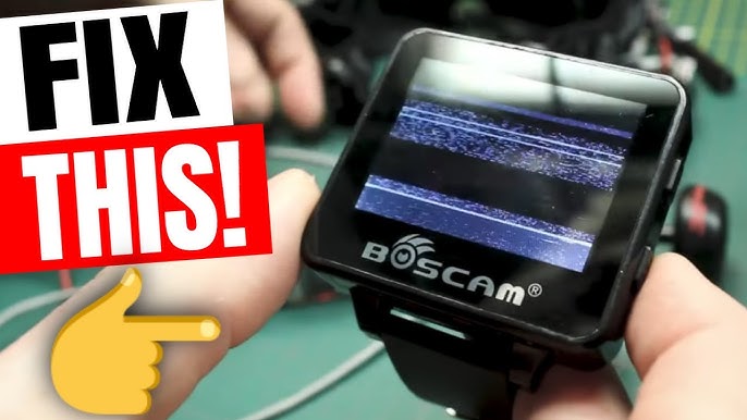
FPV Video Signal Problems: How to Diagnose and Fix Static, Blackouts, and Interference
A crystal-clear video feed is the lifeline of FPV flying. When static, blackouts, or interference strike, the experience turns from exhilarating to frustrating—and dangerous. This comprehensive guide will empower you to systematically diagnose and fix common FPV video link issues, helping you achieve a reliable and clean video signal.
Understanding Your FPV Video System
Before troubleshooting, know the chain. Your video signal travels from the Camera to the Video Transmitter (VTX), which broadcasts it via an antenna. Your drone's receiver, the Video Receiver (VRX), picks up this signal through its antenna and sends it to your goggles or screen. A failure or weakness at any point causes problems.
Phase 1: Diagnosing the Problem
Accurate diagnosis is 90% of the fix. Identify your symptom:
1. Constant Static/Snow (Poor SNR): This indicates a generally weak signal. You can still see the image, but it's noisy. Common causes are low transmission power, incorrect antenna polarization, damaged antennas, or being too far away/obstructed.
2. Complete Black Screen or "No Signal": This means a total loss of the video signal.
* At close range: Likely a hardware or power failure (camera, VTX, or connector).
* After a crash: Likely a damaged component or disconnected cable.
* At range: Your VTX may still be working, but the signal is too weak for the VRX to lock onto.
3. Sudden Blackouts or "Breakups": The video cuts in and out cleanly. This is often caused by:
* Power Issues: A brownout on the VTX or camera due to insufficient current or voltage spikes.
* Heat: VTX overheating and temporarily shutting down (thermal protection).
* Interference: Strong RF noise drowning out the signal intermittently.
4. Lines, Patterns, or Distortion in the Image:
* Horizontal Lines/Rolling: Usually electrical noise from motors or ESCs. This is "noise" in the video signal itself.
* Checkerboard or Digital Artifacts: Often points to a digital issue with the camera sensor or the connection between the camera and VTX.
Phase 2: The Step-by-Step Troubleshooting Process
Follow this logical sequence to isolate the issue.
Step 1: The Pre-Flight Checklist (Prevention)
• Antennas: Are they tightly screwed on (u.FL, SMA)? Are they the correct type (RP-SMA vs SMA)? Are they both right-hand circular polarized (RHCP) or both linear?
• Power & Band/Channel: Is your VTX powered correctly? Are your goggles set to the exact frequency/channel your VTX is broadcasting on? Use the Band, Channel, and Frequency (e.g., R8, 5917MHz) to match, not just the channel name.
Step 2: The On-Bench Test (Isolation)
Power your drone on your bench without spinning the motors.• Is the image clear? If yes, the core system works. Problems in the air likely stem from noise or antenna issues.
• Is the image bad immediately? The problem is in your core video system. Proceed to isolate:
• Camera Test: Temporarily connect the camera output directly to a monitor if possible. If the direct feed is bad, the camera is faulty.
• VTX Test: Gently touch the VTX. Is it extremely hot? It may be in a low-power mode or failing. Ensure it's set to the desired power output (e.g., 25mW, 200mW, 800mW).
• Cable Test: Flex and wiggle the wires connecting the camera to the VTX. If the image flickers, you have a bad solder joint or damaged cable.
Step 3: The In-Air Diagnosis (Noise & Interference)
If the bench test is clear, but problems appear when armed or flying:• Motor/ESC Noise: This is the #1 culprit for lines/static that worsens with throttle.
• Solution: Use a high-quality LC Filter between your power source and VTX/Camera. Ensure your VTX is powered from a clean source, like a dedicated BEC or the flight controller's filtered pad (if available).
• RF Interference: Other pilots, nearby transmitters, or even your own control link can cause interference.
• Solution: Change your VTX channel to one far from others. Use a band scanner feature on your goggles to find a clear channel. Ensure your control receiver antenna is not placed directly next to your VTX antenna.
Phase 3: Fixing Common Hardware Issues
Antenna & Connector Failures:
• The u.FL/IPEX Curse: These tiny connectors on VTXs are fragile. A crash can tear them off the PCB. If your antenna cable is loose, you may need to resolder a new u.FL pigtail or directly solder an antenna wire to the board.
• Antenna Damage: Check the active element of your antenna (the little stubbby bit on a dipole, or the sealed tip on a pagoda). If it's bent or broken, replace it. Never fly with a damaged antenna, as it can damage your VTX.
VTX Overheating and Pit Mode:
Many modern VTXs have a "pit mode" or low-power default when not armed to prevent overheating on the bench. If you have no signal on the bench, check if you need to activate "high power" via a button, OSD menu, or by arming the drone (if smart-audio/tramp is configured).
Camera Problems:• Image Quality: Adjust camera settings via the OSD menu. Poor lighting can cause a grainy image.
• No Image: Check voltage input to the camera. A 5V camera will not work on direct LiPo voltage.
Phase 4: Optimizing for Maximum Range and Clarity
Once your link is stable, optimize it.
• Antenna Placement: Mount your VTX antenna vertically, away from carbon fiber (which blocks RF) and other electronics. The "clear" tip should be in free air.
• Antenna Quality: Invest in high-gain, high-quality antennas. A good pair of directional (patch) and omnidirectional antennas for your goggles makes a huge difference.
• Power Output: Use the lowest power necessary for your flying area to reduce heat and interference. Use high power (e.g., 800mW+) for long-range or noisy environments.
• Channel Selection: The 5.8GHz band is divided into different "bands" (R, F, A, etc.). Some frequencies propagate slightly better than others in certain environments. Experiment with channels near the center of the band (e.g., Channel 4, ~5800MHz) which are often recommended.
Conclusion: A Methodical Approach to a Clear Signal
FPV video problems can be complex, but a systematic approach makes them solvable. Start by precisely identifying the symptom, then isolate the problem using bench tests. Address the most common culprits: antenna connections, power filtering for noise, and correct channel matching. Finally, optimize your antenna setup for peak performance. By following this process, you'll spend less time troubleshooting and more time enjoying a rock-solid, immersive video feed that lets you push your flying to new limits. Remember, a clear video link isn't just about quality—it's the foundation of safe and confident FPV flight.


{{ commentCount }} Comments