
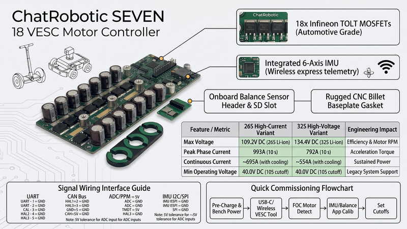
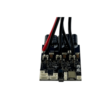
Quick Takeaway (TL;DR): The ChatRobotic SEVEN 18 is an ultra-compact, high-power-density VESC controller delivering 120V (26S) 993A peak (10 s) / 695A continuous, or 150V (32S) 792A peak (10 s) / 554A continuous, in a 145 × 65 × 30 mm (0.40 kg) package. Built on a 2-board stack with ×3 copper (4× DC-link copper weight) and an EV-derived DRV-less design, it runs 18 automotive-grade Infineon TOLT MOSFETs — IPTC017N12NM6ATMA1 (120V) on the 26S model and IPTG025N15NM6ATMA1 (150V) on the 32S model — plus an integrated 6-axis IMU, on-board Bluetooth transceiver, and CAN bus. It bridges the gap between full-scale electric motorcycle current capacity and compact self-balancing or robotic chassis constraints.
1. Engineering Architecture & High-Density Power Stage
Power density in motion control is defined by how effectively an inverter can switch high phase currents without triggering junction thermal runaway. Measuring 145 × 65 × 30 mm (0.40 kg), the SEVEN 18 delivers four-figure peak phase amperage by leveraging a parallel topology with 18 active switches (3 paralleled MOSFETs per switch position across 6 switch positions).
Power Stage & Signal Path Architecture:
•DC Power Input (40V–120V bus on the 26S model; 40V–150V bus on the 32S model)
•Multi-Stage Ceramic Decoupling Array
•Wide-Input Buck DC-DC Converter (Logic & Gate Drive Rails)
•Primary Control & Sensing Core
•Microcontroller (FOC Observer Loop @ 25kHz–50kHz)
•Integrated 6-Axis Motion Tracking IMU (Attitude / Balance Angle)
•Integrated Bluetooth Transceiver (Wireless Telemetry & Tuning)
•High-Current Power Stage
•Low-Inductance Copper Bus Planes
•18× Infineon TOLT Automotive MOSFETs (26S: IPTC017N12NM6ATMA1 · 32S: IPTG025N15NM6ATMA1)
•Top-Side Direct Thermal Interface to CNC Billet Aluminum Heatsink
•Motor Phase Output (993A Peak / 695A Continuous on 26S; 792A Peak / 554A Continuous on 32S)
Automotive-Grade TOLT MOSFET Packaging
Standard TO-220 or D2PAK packages discharge heat through their bottom drain tabs directly into the FR4 PCB, creating thermal bottlenecks. The SEVEN 18 uses Infineon TOLT (Transistor Outline Leadless Top-side cooled) packages:
•Top-Side Thermal Dissipation: Heat escapes from the exposed top metal pad directly into the CNC aluminum baseplate through a high-performance gap pad, bypassing PCB substrate thermal resistance.
•Ultralow On-State Resistance: With three devices paralleled per switch position, equivalent switch resistance drops into sub-milliohm territory. The two variants use different silicon classes, which is exactly why their current ratings differ:
•26S (120V class): R_switch_eff = R_ds(on) / 3 ≈ 1.7 mΩ / 3 ≈ 0.57 mΩ
•32S (150V class): R_switch_eff = R_ds(on) / 3 ≈ 2.5 mΩ / 3 ≈ 0.83 mΩ
•Parasitic Inductance Reduction: The leadless construction minimizes internal package lead inductance, suppressing drain-to-source inductive ringing during 50 kHz switching transients.
•Board Construction: Both variants use a 2-board assembly with ×3 copper (4× DC-link copper weight) and a DRV-less gate-drive architecture derived from EV industry practice, removing the integrated gate-driver IC as a failure point.
2. Electrical Specifications & Voltage/Current Dynamics
The SEVEN 18 is engineered in two hardware configurations to support high-voltage efficiency and high-current torque demands.
| Electrical Metric | 26S High-Current Variant | 32S High-Voltage Variant | Engineering Impact |
| Type | FOC or BLDC brushless motors | FOC or BLDC brushless motors | Supports sine-wave FOC with trapezoidal fallback. |
| Maximum Input Voltage | 120V (recommended 10S–26S) | 150V (recommended 10S–32S) | Absolute DC-bus ceiling before silicon breakdown. |
| Max Pack Voltage | 109.2V DC (26S Li-ion) | 134.4V DC (32S Li-ion) | 32S lowers phase current requirements for identical mechanical power output. |
| Silicon Rating | 120V MOSFETs (IPTC017N12NM6ATMA1) | 150V MOSFETs (IPTG025N15NM6ATMA1) | 32S keeps ~15.6V headroom above a fully charged 134.4V pack to absorb regenerative spikes. |
| MOSFET Count | 18× Infineon TOLT | 18× Infineon TOLT | 3 devices paralleled per switch position; top-side cooled. |
| Min Operating Voltage | 40.0V DC (10S) | 40.0V DC (10S) | Broad operational window allows integration with legacy 48V–72V systems. |
| Continuous Phase Current | 695A with adequate cooling | 554A with adequate cooling | Sustained uphill traction and continuous payload transport without thermal limiting. |
| Peak Phase Current (10 s) | 993A | 792A | Maximum instantaneous breakout torque for aggressive acceleration and self-balancing recovery. |
| Board Construction | 2 boards, ×3 copper (4× DC-link copper weight), DRV-less | 2 boards, ×3 copper (4× DC-link copper weight), DRV-less | Low trace resistance; eliminates gate-driver IC failure modes. |
| Input & Phase Connector | 5× screw terminals | 5× screw terminals | Screw-clamp high-current termination, no soldering required. |
| Serial Port Interface | Molex 43045 (3× 4PIN, 2× 6PIN, 1× 8PIN) | Molex 43045 (3× 4PIN, 2× 6PIN, 1× 8PIN) | Hall, encoder, UART, and peripheral expansion. |
| Programming Interface | USB-C | USB-C | Firmware flashing and VESC Tool configuration. |
| Switching Frequency | 25 kHz (up to 50 kHz) | 25 kHz (up to 50 kHz) | Eliminates audible motor whine while improving current-sampling resolution on low-inductance motors. |
| Thermal Protection Window | Soft & hard thermal limiting (75°C start – 95°C hard cutoff) | Soft & hard thermal limiting (75°C start – 95°C hard cutoff) | Linear current rollback preserves MOSFET junction integrity (T_j < 150°C). |
| Dimensions (L × W × H) | 145 × 65 × 30 mm | 145 × 65 × 30 mm | Compact footprint for high power-density integration. |
| Weight | 0.40 kg | 0.40 kg | Low mass for tight chassis packaging. |
Regenerative Braking and Inductive Spikes
During rapid decel or aggressive regenerative braking, the motor acts as a generator, pumping energy back onto the DC bus:
Bus Voltage Spike (V) = V_battery + (I_regen × R_pack_internal) + [L_harness × (di/dt)]
This is the reason the two variants exist. On the 26S model, a fully charged pack sits at 109.2V against 120V silicon — roughly 10.8V of margin. On the 32S model, a fully charged pack reaches 134.4V, which would destroy 120V silicon; the 150V devices provide about 15.6V of headroom to absorb transient overshoot. Never connect a 32S pack to the 26S model. For broader platform selection criteria, consult the complete VESC buyer's guide.
3. Benchmark Comparisons & Hardware Sizing
Selecting between high-density controllers depends on physical mounting space, required phase current, and the necessity of onboard balance sensors.
| Specification / Model | SEVEN 18 (26S / 32S) | TRONIC X12 PRO (26S / 32S) | TRONIC 250R (27S) |
| Max Input Voltage | 120V (26S) / 150V (32S) | 120V (26S) / 150V (32S) | 125V (27S) |
| Peak Current (10 s) | 993A (26S) / 792A (32S) | 662A (26S) / 380A (32S) | 300A |
| Continuous Current | 695A / 554A | 463A / 266A | 210A |
| MOSFET array | 18× IPTC017N12NM6 (26S) / 18× IPTG025N15NM6 (32S) | 12× IPTC017N12NM6 (26S) / 12× IPT039N15N5 (32S) | 6× HY5012W |
| Built-in IMU | Yes (6-axis onboard) | Yes (6-axis onboard) | Yes (6-axis onboard) |
| Wireless | Integrated Bluetooth transceiver | Integrated Bluetooth transceiver | Integrated Bluetooth |
| Dimensions (L × W × H) | 145 × 65 × 30 mm | 95 × 73 × 22 mm | 84 × 72 × 28 mm |
| Weight | 0.40 kg | 0.40 kg | 0.40 kg |
| Power Density | Extremely High | Very High | High (Budget-Optimized) |
| Primary Applications | Onewheel, Self-balancing, AGV | E-skate, EUC, Light EV | E-bikes, Scooters, Light Robotics |
| Product Link | SEVEN 18 Product Details | TRONIC X12 PRO Details | TRONIC 250R Details |
Direct Sourcing Options
•SEVEN 18 120V (26S) 993A With Case – Nylon Top, Aluminum Base – Enclosed with CNC aluminum base and rugged nylon top for harsh environments ($550.00).
•SEVEN 18 150V (32S) 792A – High-voltage bare board for custom integrated frames ($450.00).
•SEVEN 18 120V (26S) 993A – Maximum-current bare board ($450.00).
•Explore all high-power models across the ChatRobotic VESC Motor Controllers catalog.
4. Commissioning, IMU Integration & Thermal Management
•Commissioning Protocol:
•Step 1: Safe Pre-Charge & Bench Power Supply Inspection
•Step 2: USB / Bluetooth Communication via VESC Tool
•Step 3: Automated FOC Motor Parameter Detection
•Step 4: IMU Calibration & Balance App Configuration
•Step 5: Current Limits & Thermal Cutoff Mapping
Step-by-Step VESC Tool Setup
Signal Wiring Interfaces:
•CAN Bus: Multi-Controller Sync (Typical 3-Pin / JST: CAN_H, CAN_L, GND — verify pinout on board silkscreen)
•UART: Companion Computer & Display Telemetry (TX, RX, 5V, GND)
•ADC / PPM: 0–3.3V Linear Analog Throttle (ADC) / 5V-Tolerant Pulse-Position Modulation (PPM)
•Integrated IMU: Onboard 6-Axis I2C/SPI Sensor Bus routed directly to STM32/MCU
1. Initial Power Connection: Connect the controller to a current-limited DC bench supply (set to 48V–72V, 1.0A limit) or use an anti-spark connector with pre-charge resistors. Prevent input surge damage by reviewing the 72V spark and inrush current guide.
2. Firmware Link: Open VESC Tool. Establish communication via USB-C or wirelessly through the integrated Bluetooth transceiver.
3. FOC Motor Detection: Navigate to the Motor Setup Wizard:
•Measure stator resistance (R), stator inductance (L), and flux linkage (lambda).
•Run open-loop hall sensor or encoder detection.
•Apply calculated observer gains and configure the PWM switching frequency (typically 20 kHz to 30 kHz).
4. IMU Configuration (Self-Balancing & Onewheel Platforms):
•Navigate to
App Settings->IMU.•Enable the onboard IMU sensor.
•Place the vehicle on a leveled surface and run the 6-axis gyro/accelerometer calibration offset routine.
•Configure the
Balance AppPID pitch/roll control loops and roll-angle safety cutoffs.5. Throttle & Safety Settings: Set ADC throttle inputs with a minimum 5% deadband. Set
MOSFET Temp Cutoff Startto 75°C andMOSFET Temp Cutoff Endto 95°C.
Thermal Dissipation Engineering
While the aluminum baseplate dissipates thermal loads during short bursts, sustaining ~695A continuous phase current requires direct mechanical conduction:
•Mount the aluminum baseplate directly against the vehicle's structural aluminum subframe.
•Apply a non-curing thermal interface material (TIM) with a thermal conductivity rating of at least 6.0 W/m·K.
•For enclosed battery/esc compartments, ensure forced air convection or external thermal path heat sinking.
5. Target Deployments & ChatRobotic Turnkey Manufacturing
The SEVEN 18 is optimized for applications where structural volume is limited but peak phase current cannot be compromised:
•Onewheel & Self-Balancing Personal EVs: Integrated IMU eliminates external sensor breakout boards, while 993A peak current prevents nose-dives during high-speed acceleration or transition bumps.
•Heavy-Duty AGVs & Autonomous Mobile Robots (AMRs): CAN-bus multi-drop architecture allows single-chassis master controllers to coordinate multiple SEVEN 18 drives with microsecond synchronization.
•High-Torque Direct-Drive Powertrains: Seamless electrical integration with ChatRobotic LandDrive direct-drive hub motors, providing high starting torque without gearbox backlash.
•B2B Custom Hardware & NDAA Manufacturing: ChatRobotic provides full-stack OEM/ODM manufacturing services, including custom enclosure designs, modified PCB aspect ratios, NDAA-compliant electronic component sourcing, and ISO 9001 / ISO 14001 certified volume production.
Frequently Asked Questions (FAQs)
Q1: What makes the SEVEN 18 unique compared to standard 1000A-class VESC controllers?
A: Standard 1000A controllers use large footprints (exceeding 180×100 mm) with external wiring for balance sensors. The SEVEN 18 achieves 993A peak current within a 145 × 65 × 30 mm footprint by utilizing 18 top-side cooled Infineon TOLT MOSFETs and integrating a 6-axis IMU directly onto the logic plane.
Q2: How do I choose between the SEVEN 18 26S and 32S models?
A: Select the 26S model (109.2V max) for applications requiring maximum phase current (993A peak / 695A continuous) for extreme low-end torque. Select the 32S model (134.4V max / 792A peak) if your battery architecture operates above 26S to achieve higher motor RPM and lower I^2R resistive harness losses.
Q3: Can the SEVEN 18 operate reliably without an external cooling fan?
A: For intermittent burst loads (e.g., standard e-skate or Onewheel riding), passive thermal dissipation through the CNC aluminum base is sufficient. For sustained high-current commercial applications (e.g., continuous AGV towing or e-motorcycle hill climbing above 554A continuous), the baseplate must be thermally coupled to a structural aluminum chassis or forced airflow.
Q4: Does the SEVEN 18 support wireless telemetry logging without external dongles?
A: Yes. The SEVEN 18 carries an integrated Bluetooth transceiver on board, with no external dongle required. This allows real-time telemetry streaming, firmware updates, and PID parameter adjustments directly over Bluetooth via the mobile VESC Tool app.
Q5: Is the throttle ADC input 5V tolerant?
A: Yes. While the microcontroller logic operates at 3.3V, the ADC throttle input pins feature internal clamping protection making them 5V tolerant, ensuring safe integration with standard 5V hall-effect twist and thumb throttles.
Need Custom High-Power Powertrain Engineering?
Source the SEVEN 18 VESC Controller or get in touch with our engineering and hardware manufacturing team directly for custom CAD/STEP models, specialized 26S–32S+ power stages, and volume OEM/ODM inquiries: Contact ChatRobotic Engineering


{{ commentCount }} Comments