
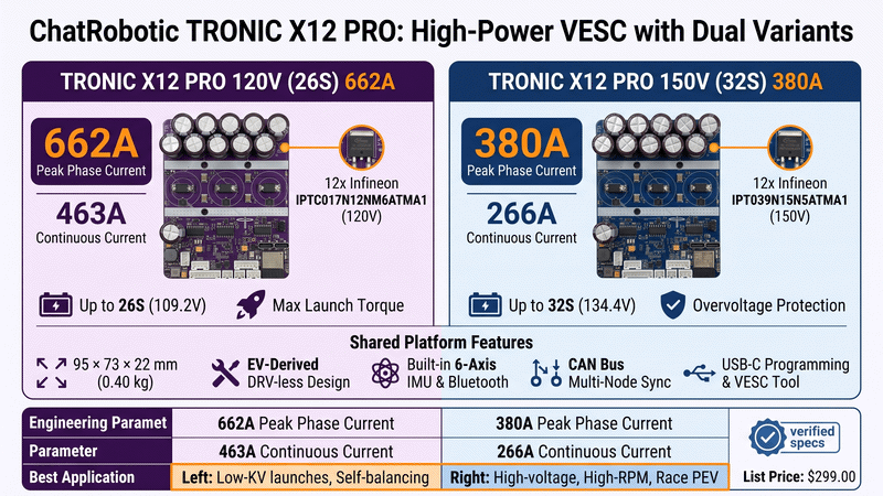
Quick Takeaway (TL;DR): The ChatRobotic TRONIC X12 PRO delivers top-tier power density in a 95 × 73 × 22 mm (0.40 kg) form factor, built on a 2-board stack with ×3 copper (4× DC-link copper weight) and an EV-derived DRV-less power stage using 12 Infineon TOLT automotive MOSFETs. Selecting between the two variants comes down to one tradeoff: silicon voltage rating versus on-resistance. Choose the TRONIC X12 PRO 120V (26S) 662A (463A continuous) for packs up to 26S where maximum launch torque and current headroom matter most; choose the TRONIC X12 PRO 150V (32S) 380A (266A continuous) for 32S / 134.4V platforms where a 150V breakdown rating is mandatory to survive regenerative overvoltage spikes. Both share identical dimensions, weight, connectors, serial interfaces, USB-C programming, onboard 6-axis IMU, Bluetooth, and CAN bus.
1. Electrical Topology & Core Architectural Tradeoffs
Selecting between the 26S and 32S variants of the TRONIC X12 PRO requires evaluating the electrical boundaries of power semiconductor physics. Both variants share an identical PCB layout, mechanical footprint (95 × 73 × 22 mm, 0.40 kg), control logic, and peripheral interface set. The engineering divergence lies in a single component choice: the MOSFET voltage breakdown rating versus its on-state resistance (R_ds(on)).
•Silicon Voltage Breakdown vs. Channel Resistance: In power MOSFET design, a higher drain-to-source breakdown voltage (V_ds) requires a thicker silicon drift layer, which naturally increases internal R_ds(on). This is not a tuning choice — it is physics, and it is the entire reason the two variants carry different current ratings.
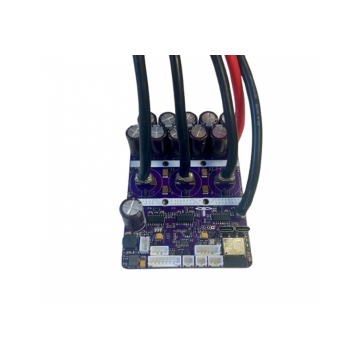
•The 26S Advantage (Higher Current Density): The 120V model uses 12× Infineon IPTC017N12NM6ATMA1 TOLT devices. The lower-resistance 120V silicon allows a 662A 10-second peak and 463A continuous rating with adequate cooling, while keeping conduction losses low.
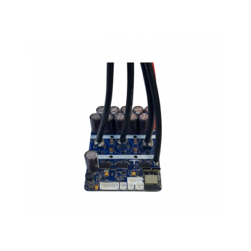
•The 32S Advantage (Higher Bus Voltage & RPM): The 150V model uses 12× Infineon IPT039N15N5ATMA1 TOLT devices. Its higher R_ds(on) limits the stage to a 380A 10-second peak and 266A continuous, but the 150V breakdown rating safely absorbs a fully charged 32S pack (134.4V) plus regenerative overshoot, while the higher bus voltage delivers greater mechanical RPM and lower I²R loss across the wiring harness.
Both boards are built as a 2-board assembly with ×3 copper (4× DC-link copper weight) and use a DRV-less design derived from EV industry practice — removing the integrated gate-driver IC (the classic DRV8301/DRV8302 failure point) in favour of discrete, robust switching.
System Sizing Sequence:
•Battery Voltage Verification
•10S–26S Pack (up to 109.2V) -> TRONIC X12 PRO 120V (26S) 662A
•10S–32S Pack (up to 134.4V) -> TRONIC X12 PRO 150V (32S) 380A
•Current & Torque Sizing
•Low-KV High-Torque Launches / Self-Balancing -> Prioritize the 120V (26S) 662A stage
•High-Speed / Direct-Drive Top End -> Prioritize the 150V (32S) 134.4V rail
•Chassis & Integration Plan
•Thermal Interface: Rated continuous current requires efficient cooling (liquid cooling or direct chassis conduction)
•Control Mapping: CAN Bus (dual-drive) or internal IMU (self-balancing)
If you are establishing foundational powertrain metrics for an entirely new project, review the complete 2026 VESC buyer's guide before finalizing your battery configuration.
2. Technical Specifications & Power Stage Deep Dive
The TRONIC X12 PRO power stage consists of 12 Infineon TOLT (Transistor Outline Leadless, Top-side cooled) automotive MOSFETs arranged in a 3-phase half-bridge (2 parallel switches per position, 4 devices per phase leg).
•Effective Switch Resistance: Parallel switch resistance is calculated by: R_switch_eff = R_ds(on) / 2
•Conduction Loss Formulation: Three-phase inverter conduction loss is modeled as: Conduction Loss (W) = 3 × (I_rms)² × R_switch_eff
•Inductive Transient Protection: During high di/dt switching transients and regenerative braking, bus voltage spikes occur: V_spike = V_battery + (I_regen × R_pack_internal) + [L_loop × (di/dt)] The 150V MOSFETs on the 32S unit maintain critical safety headroom above a fully charged 134.4V pack, protecting against transient overvoltage punch-through.
| Engineering Parameter | TRONIC X12 PRO 120V (26S) 662A | TRONIC X12 PRO 150V (32S) 380A | Engineering Impact |
| Type | FOC or BLDC brushless motors | FOC or BLDC brushless motors | Supports sine-wave FOC with trapezoidal fallback. |
| Maximum Input Voltage | 120V (recommended 10S–26S) | 150V (recommended 10S–32S) | Absolute DC-bus ceiling before silicon breakdown. |
| Max Pack Voltage (26S / 32S Li-ion) | 109.2V DC | 134.4V DC | Fully-charged battery pack potential. |
| Minimum Voltage | 40V (10S) | 40V (10S) | Operational turn-on threshold for logic and gate drive. |
| Continuous Current | 463A with adequate cooling | 266A with adequate cooling | Sustained thermal current capability under FOC control. |
| Peak Current (10 s) | 662A phase current | 380A phase current | Maximum instantaneous torque delivery for launch bursts. |
| MOSFET Part Number | 12× IPTC017N12NM6ATMA1 | 12× IPT039N15N5ATMA1 | Automotive-grade Infineon TOLT, top-side cooled. |
| Board Construction | 2 boards, ×3 copper (4× DC-link copper weight) | 2 boards, ×3 copper (4× DC-link copper weight) | Low trace resistance and superior thermal spreading. |
| Gate Driver Architecture | DRV-less (EV-derived discrete) | DRV-less (EV-derived discrete) | Eliminates gate-driver IC failure modes under switching noise. |
| Input & Phase Connector | 4× 8AWG copper lug wires (280 mm) + 1× 8AWG copper lug wire (250 mm) | 4× 8AWG wires (280 mm) + 1× 8AWG wire (250 mm) | Pre-terminated high-current copper lugs. |
| Serial Port Interface | JST PH2.0: 2× 3PIN, 2× 2PIN, 1× 4PIN, 1× 6PIN, 1× 8PIN | JST PH2.0: 2× 3PIN, 2× 2PIN, 1× 4PIN, 1× 6PIN, 1× 8PIN | Hall, encoder, UART, and peripheral expansion. |
| Programming Interface | USB-C | USB-C | Firmware flashing and VESC Tool configuration. |
| Integrated Sensors | 6-axis IMU + thermal sensor extension | 6-axis IMU + thermal sensor extension | Balance control without external gyros; external NTC support. |
| Wireless Module | Integrated Bluetooth transceiver | Integrated Bluetooth transceiver | Native mobile telemetry and parameter tuning. |
| Wired Communication | CAN bus | CAN bus | Multi-node synchronization for dual-drive architectures. |
| Switch Control | ON/OFF via any latching switch | ON/OFF via any latching switch | Clean power-down without a dedicated ESC switch. |
| Thermal Protection | Soft and hard thermal limiting | Soft and hard thermal limiting | Linear current rollback protects the MOSFET junction. |
| Enclosure Rating | IP-rated for harsh environments (dust, moisture) | IP-rated for harsh-environment deployment | Suitable for exterior vehicle mounting. |
| Dimensions (L × W × H) | 95 × 73 × 22 mm | 95 × 73 × 22 mm | Compact footprint for high power-density integration. |
| Weight | 0.40 kg | 0.40 kg | Low mass for tight chassis packaging. |
| Product SKU | CRP00230 | CRP00231 | Factory-traceable hardware production codes. |
| List Price | $299.00 (list $450.00) | $299.00 (list $450.00) | Verify current price and stock on the product page. |
3. Direct Hardware Benchmark & Sourcing
Both controllers are manufactured by an ISO 9001 and ISO 14001 certified facility and undergo functional dynamic load testing prior to delivery.
Product Selection Guide:
•Choose TRONIC X12 PRO 120V (26S) 662A
•Battery: 10S, 12S, 18S, 20S, or 26S packs (<= 109.2V)
•Priority: Maximum low-speed breakout torque, highest peak phase amps, best current-per-cubic-centimetre
•Choose TRONIC X12 PRO 150V (32S) 380A
•Battery: 10S–32S packs (<= 134.4V max)
•Priority: Regen-spike survivability at 32S, higher mechanical RPM, reduced cabling gauge, top-speed stability
A nylon-top / aluminum-base machined enclosure variant is also available for both models when structural protection and environmental sealing are required.
•Need higher current density in a similar form factor? Compare the SEVEN 18 VESC review (120V (26S) 993A / 150V (32S) 792A) to evaluate 18-MOSFET architectures.
•Exploring extreme propulsion (1000A–2000A)? Browse the complete ChatRobotic VESC Motor Controllers catalog for SEVEN 30, TRONIC 1000, and TRONIC X54 models.
4. Real-World Engineering Builds & Sizing Guide
The TRONIC X12 PRO platform is engineered to support demanding commercial, personal electric vehicle (PEV), and robotic drive architectures.
Dual-Motor High-Torque E-Skateboard
•Architecture: Dual TRONIC X12 PRO 120V (26S) units synchronized over an isolated CAN-bus network (Master ID: 0, Slave ID: 1).
•Motor Pairing: Twin 6374 or 6384 brushless outrunners (170 kV–200 kV).
•Power Dynamics: Under peak acceleration, each motor demands 60A–100A battery current. The 662A peak phase-current capacity provides substantial thermal headroom, ensuring zero thermal throttling on steep inclines.
•Build Protocol: Review the step-by-step setup in the VESC Electric Skateboard DIY Build Guide.
Onewheel & Self-Balancing Motion Systems
•Architecture: Single TRONIC X12 PRO 120V (26S) or TRONIC X12 PRO 150V (32S) utilizing the onboard 6-axis IMU.
•Firmware Integration: Flashed with the VESC ReFloat balance package. The onboard IMU delivers low-latency roll and pitch data directly to the microcontroller without external sensor breakouts.
•Safety Headroom: Instantaneous 662A / 380A peak current response guarantees torque margins during high-speed nosedives and surface transitions.
•Implementation Guide: Follow the VESC Onewheel Upgrade and Customization Guide.
32S Electric Motorcycle & High-Speed Racing Powertrains
•Architecture: Single or dual TRONIC X12 PRO 150V (32S) powering high-voltage PMSM mid-drive motors.
•Voltage Advantage: A 134.4V DC bus reduces phase current draw for equivalent kilowatt output, lowering heat generation across battery interconnects and motor windings.
•Active Cooling Integration: Mounting a liquid cooling chill plate to the flat aluminum baseplate allows continuous 266A phase-current operation during sustained track conditions.
Autonomous Mobile Robots (AMRs) & Industrial Automation
•Architecture: Distributed CAN-Bus multi-drop networks running ROS / ROS2 control nodes.
•Throttle & Control: 5V-tolerant ADC input mapped to analog controllers, with real-time positional holding and bidirectional RPM control via UART and CAN commands.
•Deployment: The IP-rated construction supports dust- and moisture-exposed industrial environments.
5. Integration Best Practices, Interfaces & ChatRobotic OEM Capabilities
Commissioning Flow:
•Step 1: Bench power-up with a current-limited supply (1.0A limit)
•Step 2: VESC Tool Motor Wizard parameter detection (R, L, Lambda)
•Step 3: FOC current loop tuning & observer gain configuration
•Step 4: IMU / throttle ADC mapping & 5% deadband setup
•Step 5: Thermal rollback configuration (75°C start / 95°C hard cutoff)
Interfaces & Thermal Sinking
1. Bare Board Form Factor (95 × 73 × 22 mm): Optimized for custom sealed battery enclosures and direct chassis heat sinking via gap pads (thermal conductivity >= 6.0 W/m·K).
2. Machined Enclosure Option: Aluminum baseplate with a rugged nylon upper shell, delivering structural protection and environmental sealing for exterior vehicle mounting.
3. Wiring: The 8AWG copper lug leads (4× 280 mm, 1× 250 mm) are pre-terminated for high-current battery and 3-phase connections; the JST PH2.0 header set carries Hall, encoder, UART, and peripheral signals.
4. Thermal Protection Protocol: Configure VESC Tool with
MOSFET Temp Cutoff Startat 75°C andMOSFET Temp Cutoff Endat 95°C. This linear rollback prevents junction over-temperature failures during continuous operation. Note that the published continuous-current figures assume efficient cooling — liquid cooling or direct chassis conduction is required to realize 463A / 266A sustained.
ChatRobotic Turnkey OEM/ODM Engineering
ChatRobotic supports global enterprise customers with custom electronic motor drive manufacturing:
•NDAA-Compliant Component Sourcing: Supply chains verified free of restricted semiconductors for commercial and defense applications.
•Custom Firmware & Communication Stacks: Customized VESC firmware forks with proprietary CAN protocols, custom throttle curves, and safety interlocks.
•Full Hardware Ecosystem Integration: Native plug-and-play pairing with ChatRobotic LandDrive (traction), AirDrive (aerial), and SeaDrive (marine) motor lines.
Frequently Asked Questions (FAQs)
Q1: Can I connect a 32S (134.4V) battery to the TRONIC X12 PRO 26S?
A: No. The TRONIC X12 PRO 120V (26S) is rated for a 120V maximum input (recommended 10S–26S). A fully charged 32S pack reaches 134.4V, which exceeds the MOSFET breakdown voltage and will destroy the power stage. Use the TRONIC X12 PRO 150V (32S) for 32S packs.
Q2: Why does the 32S model have a lower continuous and peak current rating than the 26S model?
A: Higher-voltage MOSFETs require a thicker silicon drift region, which increases internal on-resistance (R_ds(on)). Because conduction heat loss scales with resistance (P = 3 × I_rms² × R_ds(on)), the 150V power stage is rated for lower continuous (266A) and peak (380A) current than the 120V stage (463A / 662A) at the same junction temperature limit. This is why the two models use different Infineon devices: IPTC017N12NM6ATMA1 (120V) versus IPT039N15N5ATMA1 (150V).
Q3: Is the X12 PRO a DRV-less design?
A: Yes. Per the factory hardware description, the X12 PRO uses a robust DRV-less design based on EV-industry engineering practices, removing the integrated gate-driver IC entirely. This eliminates a common failure mode (gate-driver latch-up under severe switching noise) found in traditional open-source VESC hardware based on DRV8301/DRV8302.
Q4: What cooling is required to achieve the rated continuous current?
A: The factory rating explicitly states "with adequate cooling" and notes the design requires efficient cooling (e.g., liquid) for rated continuous-current performance. In passive-air installations you should de-rate the continuous figure substantially. The board supports a thermal sensor extension for direct junction monitoring.
Q5: How does the built-in IMU function on the TRONIC X12 PRO?
A: The controller features an onboard 6-axis MEMS IMU connected directly to the primary microcontroller. When running self-balancing firmware packages such as ReFloat in VESC Tool, the IMU supplies real-time pitch, roll, and angular velocity data, eliminating the need for external IMU sensor boards.
Q6: Can two TRONIC X12 PRO controllers be synchronized for dual-motor drivetrains?
A: Yes. Both units include dedicated CAN-bus transceivers. By connecting CAN_H, CAN_L, and signal ground between two controllers, you can configure one unit as Master (processing throttle and telemetry) and the second as Slave over VESC Tool with microsecond synchronization.
Q7: Is the ADC throttle input compatible with 5V Hall-effect throttles?
A: Yes. Although the microcontroller logic operates at 3.3V, the analog ADC inputs feature internal clamping and protection circuitry that makes them 5V-tolerant, allowing direct connection to standard 5V e-bike twist and thumb throttles.
Need Custom High-Power Powertrain Engineering?
Source the TRONIC X12 PRO 120V (26S) 662A or TRONIC X12 PRO 150V (32S) 380A, explore our complete VESC Motor Controllers catalog, or get in touch with our engineering and hardware manufacturing team directly for custom CAD/STEP models, specialized 26S–32S+ power stages, and volume OEM/ODM inquiries: Contact ChatRobotic Engineering


{{ commentCount }} Comments